Table of contents
This post is the third article in a series of blog posts about the Nuki Opener on the SCS bus intercom, see the Series Overview.
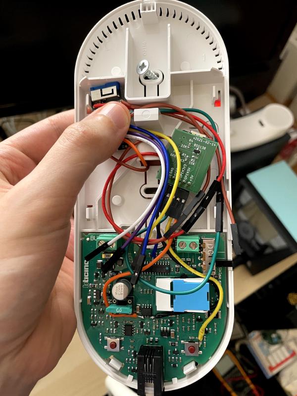
I bought the cheapest compatible BTicino intercom device (BT 344232 for 32 €) that I could find on eBay, then soldered in 4 wires and added microcontrollers to make it smart. It now connects to my Nuki Opener Smart Intercom IOT device, and to my local MQTT Pub/Sub bus (why not?).
Background
In my last post about the BTicino intercom from November, I described how to use a Teensy microcontroller to reliably interpret SCS bus signals and drive a Nuki Opener (Smart Intercom).
Originally, I had hoped the Nuki developers would be able to fix their device based on my SCS bus research, but they don’t seem to be interested. Instead, their support actually suggested I run my microcontroller workaround indefinitely!
Hence, I decided to work on the next revision to clean up my setup in terms of cable clutter. I also figured: if I already need to run my own microcontroller, I also want to connect it to my local MQTT Pub/Sub bus for maximum flexibility.
Unfortunately, the Teensy microcontroller lacks built-in WiFi, or any kind of networking.
I switched to an ESP32-based microcontroller, but powering those from the SCS bus seems like a bad idea: they draw a lot of power, and building small high-quality power supplies is hard.
This made me scrap my previous plans to make my own SCS send/receive hardware.
Instead, I wondered what the easiest yet most reliable approach might be to make this intercom unit smart. Instead of building my own SCS hardware, could I use the intercom unit itself to send the door unlock signal, and could I obtain the unit’s already-decoded SCS bus signal?
Finding the signals
Based on my previous research, I roughly knew what to expect: closest to the bus terminals, there will be some components that filter the bus signal and convert the 27V into a lower voltage. Connected to that power supply is a microcontroller which deals with all user interface.
To learn more about the components, I first identified all ICs (Integrated Circuits) based on their labeling. The following are relevant:
- TI LM393: Dual Comparators
- TI LP2951: Adjustable Micropower Voltage Regulators, 5V output
- Microchip PIC16F684: 8-bit microcontroller
I connected my development intercom unit to my SCS bus lab setup and used my oscilloscope to confirm expected signal levels based on the pinout from the IC datasheets.
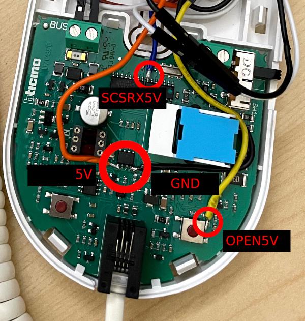
I settled on the following 4 relatively easily accessible signals and soldered jumper wires to them:
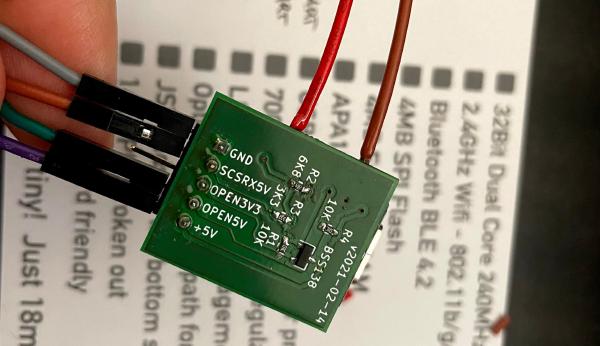
5VandGND: 5V, 100mA. Our QT Py microcontroller uses 7mA.OPEN5V: activates the button which unlocks the doorSCSRX5V: converted SCS signal
Converting the signals
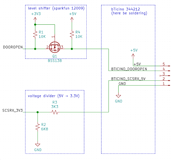
Because the BTicino intercom units runs at 5V, but more modern microcontrollers run at 3.3V, we need to convert between the two voltages:
-
We need to convert a 3.3V signal to
OPEN5Vto trigger opening the door. -
We need to convert
SCSRX5Vsignal to 3.3V so that I can use an ESP32 microcontroller to read the signal and place it on MQTT.
Here’s the corresponding schematic:
Microcontroller selection
I eventually decided to task a dedicated microcontroller with the signal conversion, instead of having the WiFi-enabled microcontroller do everything, for multiple reasons:
-
Reliability. It turns out that using a hardware analog comparator results in a much higher signal quality than continuously sampling an ADC yourself, even when using the ESP32’s ULP (Ultra Low Power) co-processor to do the sampling.
-
Easy implementation. Converting an SCS signal to a serial signal is literally a single
delayMicroseconds(20);call in the right place. Having a whole microcontroller for only this task eliminates any concurrency concerns. I have not had to debug or change the software even once in the last few months. -
Easy debugging/introspection. I can connect a standard USB-to-serial adapter and verify the signal is read correctly. This quickly narrows down issues on either side of the serial interface. Issues with the microcontroller side can be reproduced by sending serial data.
Here are the 2 microcontrollers I’m using in this project, plus the Teensy I used previously:
| Microcontroller | WiFi | Analog Comparator | Price |
|---|---|---|---|
| Teensy 4.0 | no | yes | 19 USD |
| Adafruit QT Py | no | yes | 6 USD |
| TinyPICO | yes | no | 20 USD |
If ESP32 boards such as the TinyPICO had a hardware Analog Comparator, I would likely use just one microcontroller, but keep the serial interface on a GPIO for easy debugging.
Why the Adafruit QT Py?
The minimal function we need for our signal conversion device is to convert an SCS signal (5V) to a serial signal (3.3V). For this conversion, we need a hardware analog comparator and an output GPIO that we can drive independently, so that we can modify the signal.
Additionally, the device should use as little power as possible so that it can comfortably fit in the left-over energy budget of the intercom unit’s power supply.
The smallest microcontroller I know of that comes with a hardware analog comparator is the Adafruit QT Py. It’s a 32-bit Cortex M0+ (SAMD21) that can be programmed using the Arduino IDE, or MicroPython (hence the name).
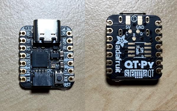
There are other SAMD21 boards with the same form factor, such as the Seeeduino XIAO.
Why the TinyPICO ESP32 board?
When looking for a WiFi-enabled microcontroller, definitely go with something ESP32-based!
The community around the Espressif ESP32 (and its predecessor ESP8266) is definitely one of its biggest pluses: there are tons of Arduino sketches, troubleshooting tips, YouTube videos, reference documentation, forum posts, and so on.
The ESPs have been around since ≈2014, so many (largely-compatible) boards are available. In fact, I started this project on an M5Stack ESP32 Basic Core IoT Development Kit, deployed it on an Adafruit HUZZAH32 Breakout Board and ultimately ported it to the TinyPICO. Porting between the different microcontrollers was really smooth: the only adjustments were pin numbers and dropping in a TinyPICO helper library for its RGB LED, which I chose to use as a power LED.
I chose the TinyPICO ESP32 board specifically for its small form factor and convenience:
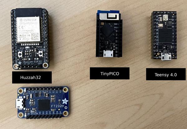
The TinyPICO is only 18mm × 32mm, slightly smaller than the Teensy 4.0’s 18mm × 35mm.
In comparison, the Adafruit HUZZAH32 breakout board is gigantic with its 25mm × 44mm. And that’s without the extra USB-to-serial adapter (FT232H in the picture above) you need for programming, serial console and powering the board!
The TinyPICO does not need an extra adapter. You can plug it in and program it immediately, just like the Teensy!
I’d like it if the next revision of the TinyPICO switched from Micro USB to USB C.
If the TinyPICO is not for you (or unavailable), search for other boards that contain the ESP32-PICO-D4 chip. For example, DFRobot’s ESP32-PICO-KIT or Espressif’s own ESP32-PICO-KIT.
Prototype
After testing everything on a breadboard, I soldered a horizontal pin header onto the QT Py, connected it to my Sparkfun level shifter board and soldered the remaining voltage divider components “flying”. The result barely fit into the case, but worked flawlessly for weeks:
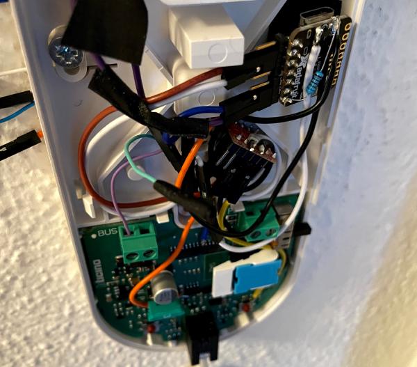
Backpack PCB for the QT Py
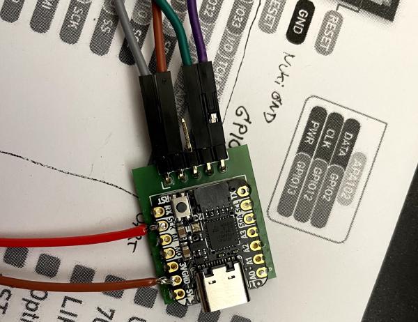
After verifying this prototype works well in practice, I miniaturized it into a “backpack” PCB.
The backpack contains all the same parts as the prototype, but with fewer bulky wires and connectors, and using only SMD parts. The build you see below uses 0602 SMD parts, but if I made another revision I would probably chose the larger 0805 parts for easier soldering.
Assembly
To save some space in the intercom unit case, I decided to solder the jumper wires directly onto the TinyPICO instead of using a pin header. I could have gone one step further by cutting the wires at length and soldering them directly on both ends, without any connectors, but I wanted to be able to easily unplug and re-combine the parts of this project.
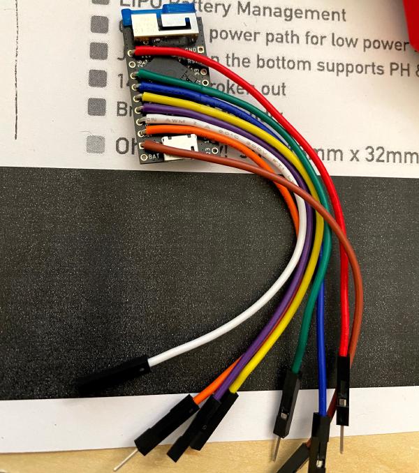
From top to bottom, I made the following connections:
| Pin | Color | Function |
|---|---|---|
| 25 | red | SCSRX_3V3 |
| 27 | green | OPEN_3V3 |
| 15 | blue | Nuki Opener blue cable |
| 14 | yellow | Nuki Opener yellow cable |
| 4 | purple | floor ring button pushed |
| 3V3 | white | 3.3V for the floor ring button |
| 5V | orange | power for the TinyPICO |
| GND | brown | ground for the TinyPICO |
| GND | brown | ground to the QT Py |
| GND | brown | ground to the Nuki Opener |
The TinyPICO USB port is still usable for updating the software and serial console debugging.
Here’s the TinyPICO connected to the QT Py inside the intercom unit:

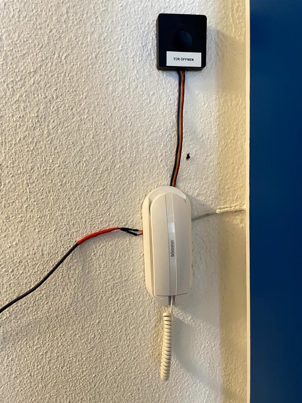
The QT Py is powered by the intercom unit’s supply, and the TinyPICO I’m powering with an external USB power supply and a cut-open USB cable. This allows me to route the jumper wires through the intercom unit’s hole in the back, through which a USB plug doesn’t fit:
Software / Artifacts
You can find the Arduino sketches and KiCad files for this project at https://github.com/stapelberg/intercom-backpack
For debugging, I found it useful to publish every single byte received from the
SCS bus on the doorbell/debug/scsrx MQTT topic. Full SCS telegrams are
published to doorbell/events/scs, so by observing both, you can verify that
retransmission suppression and SCS decoding work correctly.
Similarly, signaling a doorbell ring to the Nuki Opener can be debugged by
sending a message to MQTT topic doorbell/debug/cmd/ring.
Initially, it wasn’t clear to me whether the WiFi library would maintain the
connection indefinitely. After observing my microcontroller eventually
disappearing from my network, I added the taskreconnect FreeRTOS task, and
things have been stable since.
Nuki Opener: verdict
I now have a Nuki Opener running next to my own microcontroller, so I can see how well it works.
setup
Setting up the Nuki is the worst part: their colorful cable is super flimsy and loose, often losing contact. They should definitely switch to a cable with a mechanical lock.
The software part of the setup is okay, but the compatibility with the SCS bus is poor: I couldn’t get the device to work at all (see my initial post), and had to resort to using my own microcontroller to drive the Nuki in analogue mode.
I’m disappointed that the Nuki developers aren’t interested in improving their device’s compatibility and reliability with the SCS bus. They seem to capture/replay the entire signal (including re-transmissions) instead of actually decoding the signal.
in my day-to-day
The push notifications I get on my iPhone from the Nuki are often delayed. Usually the delay is a few seconds, but sometimes notifications arrive hours later or just don’t arrive at all!
While the push notifications are sent from a Nuki server and hence need the internet to function, the Nuki Bridge (translating Bluetooth Low Energey from the Nuki Opener to WiFi) allows configuring notifications in the local network via web hooks.
The Nuki Bridge’s notifications are much more reliable in my experience.
People sometimes ask why I use the Nuki Opener at all, given that I have some infrastructure of my own, too. While opening the door and receiving notifications is something I can do without the Nuki, too, I don’t want to spend my spare time re-implementing the Nuki app (on multiple platforms) with its geo fencing, friend invitations, ring to open, etc. In addition, the Nuki Opener physical device has a nice ring sound and large push button to open the door, both of which are convenient.
Conclusion
My intercom is now much smarter! Doorbell notifications make their way to my various devices via MQTT, and I can conveniently open the door from any device, as opposed to rushing to the intercom unit in the hallway.
Compared to the previous proof-of-concepts and development installations, I feel more confident in the current solution because it re-uses the intercom unit for the nitty-gritty SCS bus communication details.
The overall strategy should be widely applicable regardless of the specific intercom vendor/unit you have. Be sure to buy your own unit (don’t solder into your landlord’s intercom unit!) and test in a separate lab setup first, of course!
Appendix A: Troubleshooting
To debug the problem of ring detection no longer working, check:
- Is the ESP32 still working?
ping doorbelltpmosquitto_pub -h dr -t 'doorbell/debug/cmd/ring' -m '3'should signal a ring to the Nuki Opener and result in events on the MQTT bus
- Is the QT Py still working?
- Its power LED should be off. If the LED is on, the QT Py is in the bootloader.
- Unplug and replug the
+5Vwire to the QT Py, see if that fixes it. - Connect a USB-to-serial adapter and see if triggering a door open results in SCS bytes on the serial interface.
- See if ringing the bell results in SCS bytes on the serial interface. If no, re-solder cable to
SCSRX5V.
To debug the problem of door opening no longer working, check:
- Does it work when triggering it via the button on the BTicino? If yes, re-solder cable to
OPEN5V.
Did you like this post? Subscribe to this blog’s RSS feed to not miss any new posts!
I run a blog since 2005, spreading knowledge and experience for over 20 years! :)
If you want to support my work, you can buy me a coffee.
Thank you for your support! ❤️