Table of contents
This post is the second article in a series of blog posts about the Nuki Opener on the SCS bus intercom, see the Series Overview.
I recently bought a Nuki Opener, which “turns your existing intercom into a smart door opener”.
Unfortunately, I have had a lot of trouble getting it to work.
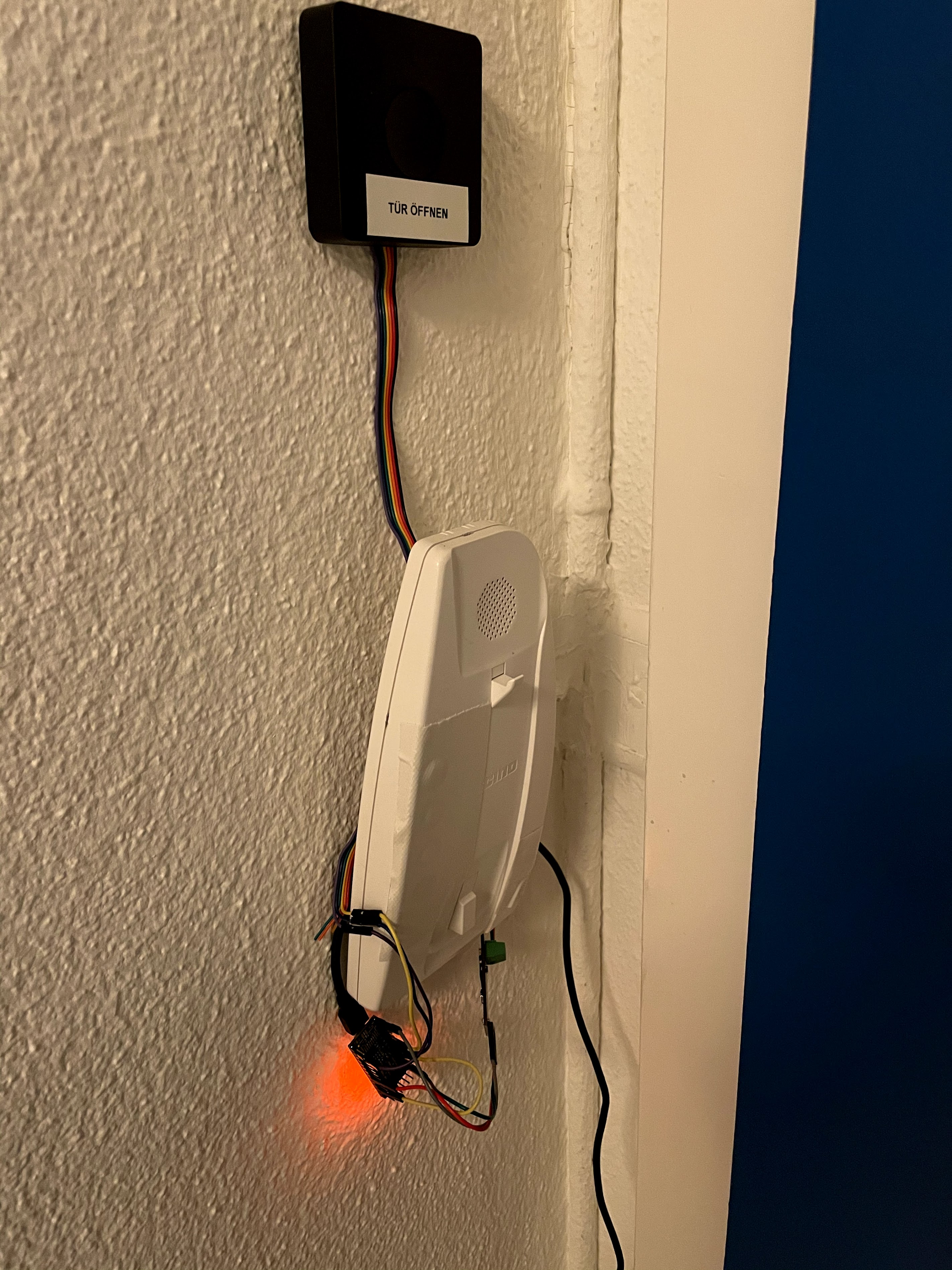
I finally got the device working by interjecting my own micro controller between the intercom bus and the Nuki Opener, then driving the Nuki Opener in its Analogue mode:
The rest of this article outlines how this setup works at a high level.
Prerequisites
For reliable interpretation and transmission of SCS bus data, we’ll need:
-
SCS receive/transmit circuits. These can be prototyped on a breadboard if you have the required diodes, transistors, resistors and capacitors.
-
A microcontroller with an Analog Comparator. If your microcontroller has one, you’ll find a corresponding section in the datasheet. This function is sometimes abbreviated to
CMPorAC, or might be part of a larger Analog/Digital Converter (ADC). -
A UART (serial) decoder. Most microcontrollers have at least one UART, but if you don’t have one available for whichever reason, you could use a software UART implementation, too.
SCS receive circuit

An R-C network, directly connected to the SCS bus, is used for incoming signal conditioning.
The resistor values have been chosen to divide the voltage of the input signal from 28V down to approx. 2V, i.e. well within the 0-3.3V range for modern microcontroller GPIO pins.
A zener diode limits the 28V level to 3.3V, which should be safe for most microcontrollers.
Simulation: https://tinyurl.com/yxhrkejn
SCS transmit circuit

We directly connect the gate of a mosfet transistor to a GPIO pin of our microcontroller, so that when the microcontroller drives the pin high, we use the 100Ω resistor to attach a load to the SCS bus.
For comparison, the KNX bus, which is similar to the SCS bus, uses a 68Ω resistor here.
Simulation: https://tinyurl.com/y6nv4yg7
SCS lab setup
Use a lab power supply to generate 28V DC. I’m using the Velleman LABPS3005SM because it was in stock at Galaxus, but any power supply rated for at least 30V DC will do.
As the DIY home automation blog entry “A minimal KNX setup” describes, you’ll need to place a 47Ω resistor between the power line and your components.
Afterwards, just connect your components to the bus. The supply/ground line of a breadboard will work nicely.

Micro Controller choice
In this blog post, I’m using a Teensy 4 development board that is widely available for ≈20 USD:

With its 600 MHz, the Teensy 4 has enough sheer clock frequency to allow for sloppier coding while still achieving high quality input/output.
The teensy tiny form factor (3.5 x 1.7 cm) works well for this project and will allow me to store the microcontroller in an existing intercom case.
The biggest downside is that NXP’s own MCUXpresso IDE cannot target the Teensy 4!
The only officially supported development environment for the Teensy 4 is Teensyduino, which is a board support package for the Arduino IDE. Having Arduino support is great, but let’s compare:
I also have NXP’s MIMXRT1060-EVK eval kit, which uses the same i.MX RT1060 micro controller family as the Teensy 4, but is much larger and comes with all the bells and whistles; notably:
- The MCUXpresso IDE works with the eval kit’s built-in debugger out of the box! Being able to inspect a stack trace, set breakpoints and look at register contents are invaluable tools when doing micro controller development.
- The MCUXpresso IDE comes with convenient graphical Pin and Clock config tools. Setting a pin’s alternate function becomes a few clicks instead of hours of fumbling around.
- The NXP SDK contains a number of drivers and examples that are tested on the eval kit. That makes it really easy to get started!
Each of these points is very attractive on their own, but together they make the whole experience so different!
Being able to deploy to the Teensy from MCUXpresso would be a killer feature! So many NXP SDK examples would suddenly become available, filling the Teensy community’s gaps.
Signal Setup
On a high level, this is how we are going to connect the various signals:
Step 1. We start with the SCS intercom bus signal (28V high, 22V low):
Step 2. Our SCS receive circuit takes the bus signal and divides it down to 2V:

Step 3. We convert the voltage-divided analog signal into a digital SCSRXOUT signal:

Step 4. We modify our SCSRXOUT signal so that it can be sampled at 50%:

Step 5. We decode the signal using our micro controller’s UART:

Micro Controller firmware
Once I complete the next revision of the SCS interface PCB, I plan to release all design files, schematics, sources, etc. in full.
Until then, the following sections describe how the most important parts work, but skip over the implementation-specific glue code that wires everything together.
Analog Comparator
The Analog Comparator in our microcontroller lets us know whether a voltage is above or below a configured threshold voltage by raising an interrupt. A good threshold is 1.65V in my case.
In response to the voltage change, we set GPIO pin 15 to a digital high (3.3V) or low (0V) level:
volatile uint32_t cmpflags;

// ISR (Interrupt Service Routine), called by the Analog Comparator:
void acmp1_isr() {
  cmpflags = CMP1_SCR;

  { // clear interrupt status flags:
    uint8_t scr = (CMP1_SCR & ~(CMP_SCR_CFR_MASK | CMP_SCR_CFF_MASK));
    CMP1_SCR = scr | CMP_SCR_CFR_MASK | CMP_SCR_CFF_MASK;
  }

  if (cmpflags & CMP_SCR_CFR_MASK) {
    // See below! This line will be modified:
    digitalWrite(15, HIGH);
  }

  if (cmpflags & CMP_SCR_CFF_MASK) {
    digitalWrite(15, LOW);
  }
}
This signal can easily be verified by attaching an oscilloscope probe each to
the SCSRX voltage-regulated bus signal input and to the SCSRXOUT GPIO pin
output:
Analog Comparator Modification
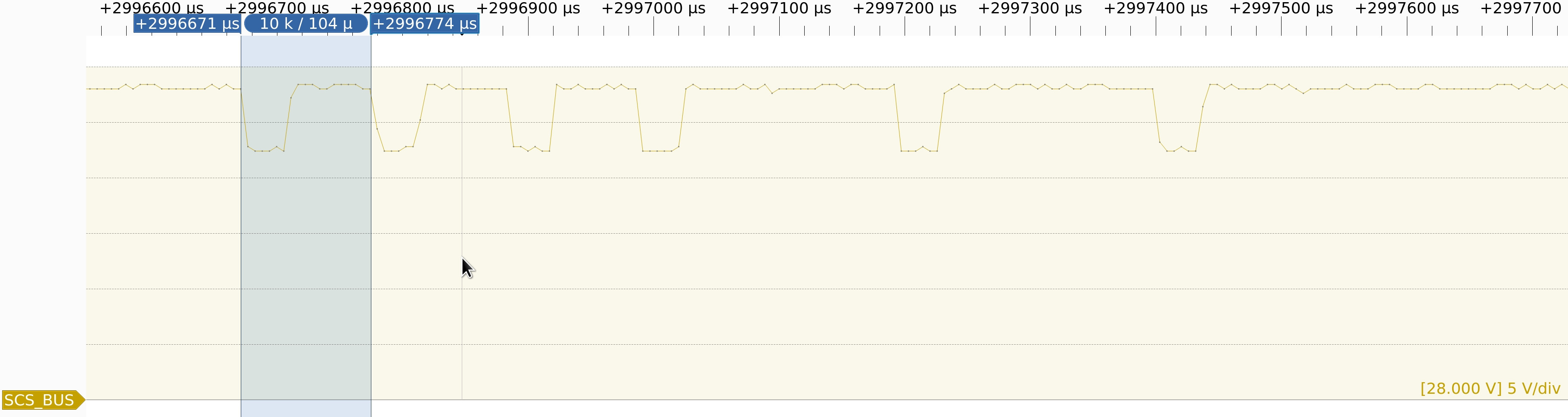
There is one crucial difference between SCS and UART:
To transmit a 0 (or start bit):
- SCS is low 34μs, then high 70μs
- UART is low the entire 104μs
UART implementations typically sample at 50%, the middle of the bit period.
For SCS, we would need to sample at 20%, because the signal returns to high so quickly.
While setting a custom sample point is possible in e.g. sigrok’s UART decoder, neither software nor hardware serial implementations on micro controllers typically support it.
On a micro controller it is much easier to just modify the signal so that it can be sampled at 50%.
In practical terms, this means modifying the acmp1_isr function to return to
high later than the Analog Comparator indicates:
volatile uint32_t cmpflags;

// ISR (Interrupt Service Routine), called by the Analog Comparator:
void acmp1_isr() {
  cmpflags = CMP1_SCR;

  { // clear interrupt status flags:
    uint8_t scr = (CMP1_SCR & ~(CMP_SCR_CFR_MASK | CMP_SCR_CFF_MASK));
    CMP1_SCR = scr | CMP_SCR_CFR_MASK | CMP_SCR_CFF_MASK;
  }

  if (cmpflags & CMP_SCR_CFR_MASK) {
    // Instead of setting our output pin high immediately,
    // we delay going up by approx. 40us,
    // turning the SCS signal into a UART signal:
    delayMicroseconds(40);
    digitalWrite(15, HIGH);
  }

  if (cmpflags & CMP_SCR_CFF_MASK) {
    digitalWrite(15, LOW);
  }
}
You can now read this signal using your laptop and a USB-to-serial adapter!
On a micro controller, we now feed this signal back into a UART decoder. For prototyping, this can literally mean a jumper wire connecting the output GPIO pin with a serial RX pin. Some micro controllers also support internal wiring of peripherals, allowing you to get rid of that cable.
SCS RX (receive)
With the SCS intercom bus signal bytes now available through the UART decoder, we can design a streaming SCS decoder. The decoder self-synchronizes and skips invalid SCS telegrams by checking their checksum. We start with a ring buffer and a convenience working copy:
constexpr int telegramLen = 7;

typedef struct {
  // circular buffer for incoming bytes, indexed using cur
  uint8_t buf[telegramLen];
  int cur;

  uint8_t tbuf[telegramLen];
} scsfilter;
Each byte we receive from the UART, we store in our ring buffer:
void sf_WriteByte(scsfilter *sf, uint8_t b) {
  sf->buf[sf->cur] = b;
  sf->cur = (sf->cur + 1) % telegramLen;
}
After every byte, we can check if the ring buffer decodes to a valid ring signal SCS bus telegram:
bool sf_completeAndValid(scsfilter *sf) {
  const uint8_t prev = sf->buf[(sf->cur+(telegramLen-1))%telegramLen];
  if (prev != 0xa3) {
    return false; // incomplete: previous byte not a telegram termination
  }

  // Copy the whole telegram into tbuf; makes working with it easier:
  for (int i = 0; i < telegramLen; i++) {
    sf->tbuf[i] = sf->buf[(sf->cur+i)%telegramLen];
  }

  const uint8_t stored = sf->tbuf[5];
  const uint8_t computed = sf->tbuf[1] ^
    sf->tbuf[2] ^
	sf->tbuf[3] ^
	sf->tbuf[4];
  if (stored != computed) {
    return false; // corrupt? checksum mismatch
  }

  return true;
}

int sf_ringForApartment(scsfilter *sf) {
  if (!sf_completeAndValid(sf)) {
    return -1;
  }

  if (sf->tbuf[3] != 0x60) {
    return -1; // not a ring command
  }

  if (sf->tbuf[1] != 0x91) {
    return -1; // not sent by the intercom house station
  }

  return (int)(sf->tbuf[2]); // apartment id
}
SCS TX (send)
Conceptually, writing serial data to a GPIO output from software is done with e.g. the Arduino SoftwareSerial library, but there are plenty of implementations for different micro controllers. This technique is also sometimes called “Bit banging”.
I started with the the Teensy SoftwareSerial::write
implementation
and modified it to:
-
Invert the output to drive the SCS transmit circuit’s Mosfet transistor gate, i.e. low on idle and high on transmitting a 0 bit.
-
Return to idle 70μs earlier than the signal would, i.e. after ≈34μs already.
The modified write function looks like this:
#define V27 LOW
#define V22 HIGH

#define scs0() do { \
  while (ARM_DWT_CYCCNT - begin_cycle < (target-43750/*70us*/)) ; \
  digitalWriteFast(11, V27); \
} while (0)

size_t SCSSerial::write(uint8_t b)
{
  elapsedMicros elapsed;
  uint32_t target;
  uint8_t mask;
  uint32_t begin_cycle;

  ARM_DEMCR |= ARM_DEMCR_TRCENA;
  ARM_DWT_CTRL |= ARM_DWT_CTRL_CYCCNTENA;
  ARM_DWT_CYCCNT = 0;

  // start bit
  target = cycles_per_bit;
  noInterrupts();
  begin_cycle = ARM_DWT_CYCCNT;
  digitalWriteFast(11, V22);
  scs0();
  wait_for_target(begin_cycle, target);

  // 8 data bits
  for (mask = 1; mask; mask <<= 1) {
    if (b&mask) {
      digitalWriteFast(11, V27);
    } else {
      digitalWriteFast(11, V22);
    }
    target += cycles_per_bit;
    scs0();
    wait_for_target(begin_cycle, target);
  }

  // stop bit
  digitalWriteFast(11, V27);
  interrupts();
  target += cycles_per_bit;
  scs0();
  while (ARM_DWT_CYCCNT - begin_cycle < target) ; // wait
  return 1;
}
It works!
With the approach described above, I now have a micro controller that recognizes doorbell rings for my apartment and ignores doorbell rings for my neighbors. The micro controller can unlock the door, too, and both features are available through the Nuki Opener.
How is the Nuki Opener?
It took over 2 months before I saw the Nuki Opener working correctly for the first time.
I really hope the Nuki developers can work with what I described above and improve their product’s reliability for all customers with an SCS intercom system!
The device itself seems useful and usable, but time will tell how reliable it turns out in practice. I think I noticed push notifications when the door rang coming in rather late (many seconds later).
I’ll keep an eye on this and explore the various Nuki APIs more.
Update (January 2023): The doorbell push notification typically arrives within seconds of the doorbell ring, but sometimes there is a noticeable delay of tens of seconds — definitely long enough for the delivery person to lose patience. I’m glad I have my MQTT-based solution which has a <1s delay.
Next up
The third article in this series is Make your intercom smarter with an MQTT backpack.
Appendix: Project Journal
- 2020-09-26: I buy a Nuki Opener (Nuki Opener #1), but despite connecting it correctly, it never successfully opens the door. I start learning about the SCS home automation bus system that our intercom uses.
- 2020-09-28: I publish an SCS bus decoder for sigrok and contact the Nuki Support.
- 2020-10-15: I buy another Nuki Opener (Nuki Opener #2) to test their old firmware version, because downgrading firmware versions is impossible. Opener #2 actually opens the door, so I assume we are dealing with a firmware problem [turns out incorrect later].
- 2020-10-16: I publish a detailed analysis of the Nuki Opener not sending the correct signal for the Nuki developers to go through.
- 2020-11-03: I update my new Nuki Opener #2 to the latest firmware and realize that my old Nuki Opener #1 most likely just has some sort of hardware defect. However, Opener #2 has trouble detecting the ring signal: either it doesn’t detect any rings at all, or it detects all rings, including those for my neighbors!
- 2020-11-16: In their 13th (!) email reply, Nuki Support confirms that the Opener firmware is capturing and matching the incoming ring signal, if I understand their developers correctly.
- 2020-11-18: I suggest to Nuki developers (via Nuki Support) to decode the SCS signal with a UART decoder instead of comparing waveforms. This should be a lot more reliable!
- 2020-11-23: My self-designed SCS receiver/transmitter/power supply PCB arrives. The schematics are based on existing SCS DIY work, but I created my own KiCad files because I was only interested in the SCS bus interface, not the PIC microcontroller they used.
- 2020-11-25: Working on the intercom, I assume some wire touched an unlucky spot, and my BTicino intercom went up in smoke. We enabled the Nuki Opener’s ring sound and started using it as our main door bell. This meant we now started hearing the ring sound for (some) of our neighbors as well.
- 2020-11-26: My Teensy 4 microcontroller successfully decodes the SCS bus signal with its Analog Comparator and UART decoder.
- 2020-11-28: My Teensy 4 microcontroller is deployed to filter the SCS bus ring signal and drive the Nuki Opener in analogue mode.
Did you like this post? Subscribe to this blog’s RSS feed to not miss any new posts!
I run a blog since 2005, spreading knowledge and experience for over 20 years! :)
All of my content is human-authored. I do use LLMs for research and knowledge work, and even to review my posts, but all writing is my own, every word is my own voice.