<?xml version="1.0" encoding="utf-8"?>
<feed xmlns="http://www.w3.org/2005/Atom">
  <title>Michael Stapelbergs Website: posts tagged kinx</title>
  <link href="https://michael.stapelberg.ch/posts/tags/kinx/feed.xml" rel="self"/>
  <link href="https://michael.stapelberg.ch/posts/tags/kinx/"/>


  <id>https://michael.stapelberg.ch/posts/tags/kinx/</id>
  <author>
    <name>Michael Stapelberg</name>
  </author>
  <generator>Hugo -- gohugo.io</generator>
  <entry>
    <title type="html"><![CDATA[Measure and reduce keyboard input latency with QMK on the Kinesis Advantage]]></title>
    <link href="https://michael.stapelberg.ch/posts/2021-05-08-keyboard-input-latency-qmk-kinesis/"/>
    <id>https://michael.stapelberg.ch/posts/2021-05-08-keyboard-input-latency-qmk-kinesis/</id>
    <published>2021-05-08T15:57:00+02:00</published>
    <content type="html"><![CDATA[<p>Over the last few years, I worked on a few projects around keyboard input latency:</p>
<p>In 2018, I introduced the <a href="/posts/2018-04-17-kinx/">kinX keyboard controller with 0.2ms of input
latency</a>.</p>
<p>In 2020, I introduced the <a href="/posts/2020-07-09-kint-kinesis-keyboard-controller/">kinT keyboard
controller</a>, which works
with a wide range of Teensy micro controllers, and both the old KB500 and the
newer KB600 Kinesis Advantage models.</p>
<p>While the 2018 kinX controller had built-in latency measurement, I was starting
from scratch with the kinT design, where I wanted to use the QMK keyboard
firmware instead of my own firmware.</p>
<p>That got me thinking: instead of adjusting the firmware to self-report latency
numbers, is there a way we can do latency measurements externally, ideally
without software changes?</p>
<p>This article walks you through how to set up a measurement environment for your
keyboard controller’s input latency, be it original or self-built. I’ll use a
Kinesis Advantage keyboard, but this approach should generalize to all
keyboards.</p>
<p>I will explain a few common causes for extra keyboard input latency and show you
how to fix them in the QMK keyboard firmware.</p>
<h2 id="measurement-setup">Measurement setup</h2>
<p>The idea is to connect a <a href="https://www.pjrc.com/store/teensy40.html">Teensy 4.0</a>
(or similar), which simulates pressing the Caps Lock key and measures the
duration until the keypress resulted in a Caps Lock LED change.</p>
<p>We use the Caps Lock key because it is one of the few keys that results in an
LED change.</p>
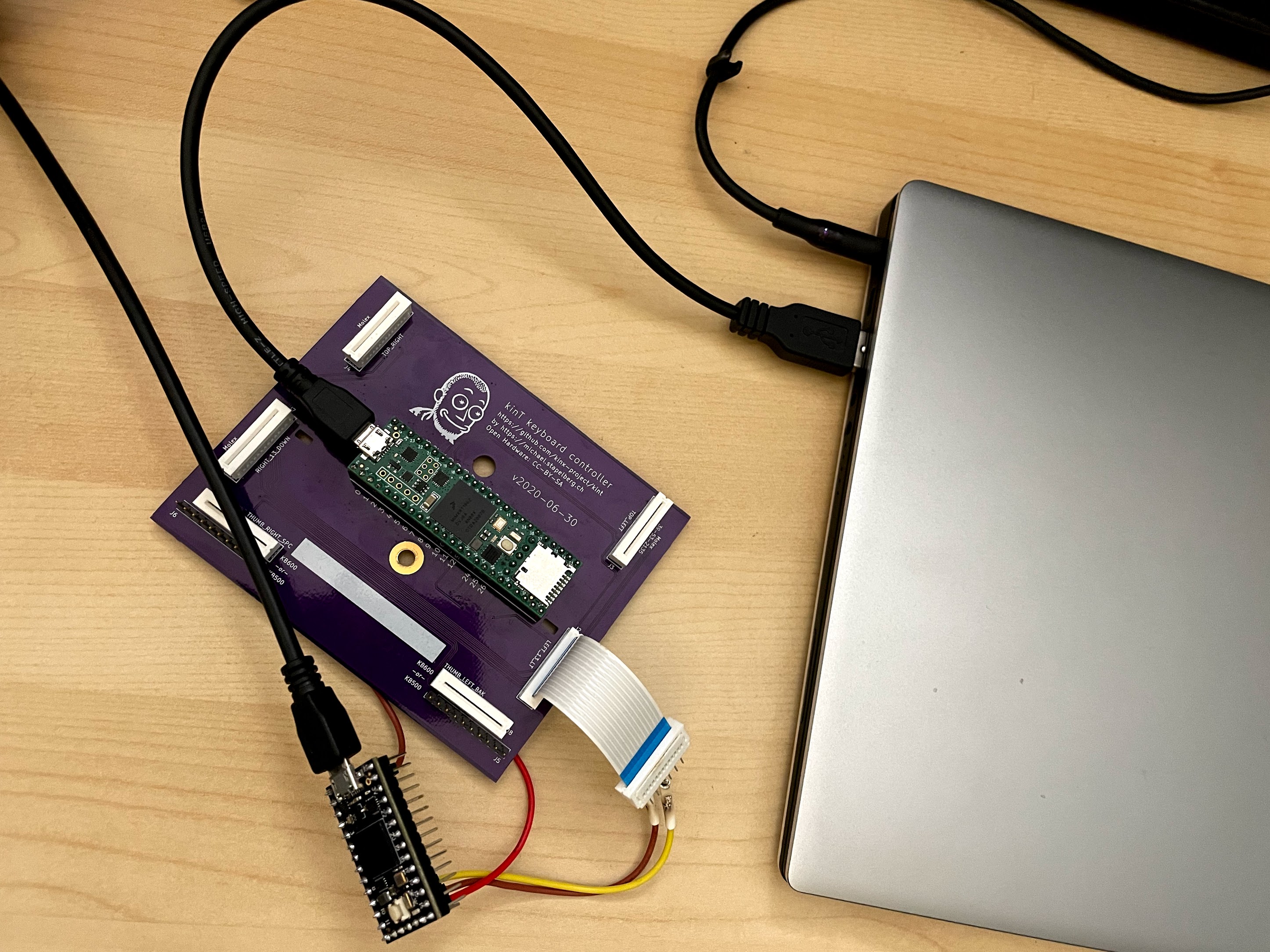
<p>Here you can see the Teensy 4.0 connected to the <a href="https://github.com/kinx-project/kint/">kinT
controller</a>, connected to a laptop:</p>


<a href="https://michael.stapelberg.ch/posts/2021-05-08-keyboard-input-latency-qmk-kinesis/endtoend_measure_featured.jpg"><img
  srcset="https://michael.stapelberg.ch/posts/2021-05-08-keyboard-input-latency-qmk-kinesis/endtoend_measure_featured_hu_355b2d65e964d2ec.jpg 2x,https://michael.stapelberg.ch/posts/2021-05-08-keyboard-input-latency-qmk-kinesis/endtoend_measure_featured_hu_504a622ead42bc76.jpg 3x"
  src="https://michael.stapelberg.ch/posts/2021-05-08-keyboard-input-latency-qmk-kinesis/endtoend_measure_featured_hu_46d0fab601e0fa0b.jpg"
  alt="measurement setup" title="measurement setup"
  width="600"
  height="450"
  style="

border: 1px solid #000;

"
  
  loading="lazy"></a>


<h3 id="enable-the-debug-console-in-qmk">Enable the debug console in QMK</h3>
<p>Let’s get our QMK working copy ready for development! I like to work in a
separate QMK working copy per project:</p>
<pre tabindex="0"><code>% docker run -it -v $PWD:/usr/src archlinux
# pacman -Sy &amp;&amp; pacman -S qmk make which diffutils python-hidapi python-pyusb
# cd /usr/src
# qmk clone -b develop qmk/qmk_firmware $PWD/qmk-input-latency
# cd qmk-input-latency
</code></pre><p>I compile the firmware for my keyboard like so:</p>
<pre tabindex="0"><code># make kinesis/kint36:stapelberg
</code></pre><p>To enable the debug console, I need to edit my QMK keymap <code>stapelberg</code> by
updating <code>keyboards/kinesis/keymaps/stapelberg/rules.mk</code> to contain:</p>
<pre tabindex="0"><code>CONSOLE_ENABLE = yes
</code></pre><p>After compiling and flashing the firmware, the <code>hid_listen</code> tool will detect the
device and listen for QMK debug messages:</p>
<pre tabindex="0"><code>% sudo hid_listen
Waiting for device:...
Listening:
</code></pre><h3 id="finding-the-pins">Finding the pins</h3>
<p>Let’s locate the Caps Lock key’s corresponding row and column in our keyboard matrix!</p>
<p>We can make QMK show which keys are recognized after each scan by adding to
<code>keyboards/kinesis/keymaps/stapelberg/keymap.c</code> the following code:</p>
<div class="highlight"><pre tabindex="0" style="background-color:#f0f0f0;-moz-tab-size:4;-o-tab-size:4;tab-size:4;-webkit-text-size-adjust:none;"><code class="language-c" data-lang="c"><span style="display:flex;"><span><span style="color:#902000">void</span> <span style="color:#06287e">keyboard_post_init_user</span>() {
</span></span><span style="display:flex;"><span>  debug_config.enable <span style="color:#666">=</span> <span style="color:#007020">true</span>;
</span></span><span style="display:flex;"><span>  debug_config.matrix <span style="color:#666">=</span> <span style="color:#007020">true</span>;
</span></span><span style="display:flex;"><span>}
</span></span></code></pre></div><p>Now we’ll see in the <code>hid_listen</code> output which key is active when pressing Caps Lock:</p>
<pre tabindex="0"><code>r/c 01234567
00: 00100000
01: 00000000
[…]
</code></pre><p>For our kinT controller, Caps Lock is on QMK matrix row 0, column 2.</p>
<p>In the <a href="https://github.com/kinx-project/kint/blob/master/schematic-v2021-04-25.pdf">kinT
schematic</a>,
the corresponding signals are <code>ROW_EQL</code> and <code>COL_2</code>.</p>
<p>To hook up the Teensy 4.0 latency measurement driver, I am making the following
GPIO connections to the kint36, kint41 or kint2pp (with voltage converter!)
keyboard controllers:</p>
<table>
	<thead>
			<tr>
					<th>driver 4.0</th>
					<th>signal</th>
					<th>kint36, kint41</th>
					<th>kint2pp (5V!)</th>
			</tr>
	</thead>
	<tbody>
			<tr>
					<td>GND</td>
					<td><code>GND</code></td>
					<td>GND</td>
					<td>GND</td>
			</tr>
			<tr>
					<td>pin 10</td>
					<td><code>ROW_EQL</code></td>
					<td>pin 8</td>
					<td>D7</td>
			</tr>
			<tr>
					<td>pin 11</td>
					<td><code>COL_2</code></td>
					<td>pin 15</td>
					<td>F7</td>
			</tr>
			<tr>
					<td>pin 12</td>
					<td><code>LED_CAPS_LOCK</code></td>
					<td>pin 12</td>
					<td>C1</td>
			</tr>
	</tbody>
</table>
<aside class="admonition note">
  <div class="note-container">
    <div class="note-icon" style="width: 20px; height: 20px">
      <svg id="exclamation-icon" width="100%" height="100%" viewBox="0 0 24 24" version="1.1" xmlns="http://www.w3.org/2000/svg" xmlns:xlink="http://www.w3.org/1999/xlink" xml:space="preserve" style="fill-rule:evenodd;clip-rule:evenodd;stroke-linejoin:round;stroke-miterlimit:1.41421;">
    <path d="M0,0L24,0L24,24L0,24L0,0Z" style="fill:none;"/>
    <g transform="matrix(1.2,0,0,1.2,-2.4,-2.4)">
        <path d="M12,2C6.48,2 2,6.48 2,12C2,17.52 6.48,22 12,22C17.52,22 22,17.52 22,12C22,6.48 17.52,2 12,2ZM13,17L11,17L11,15L13,15L13,17ZM13,13L11,13L11,7L13,7L13,13Z" style="fill-rule:nonzero;"/>
    </g>
</svg>

    </div>
    <div class="admonition-content"><strong>Note:</strong> Unfortunately, the signals are not available on the Teensy 4.x dev kit
<a href="https://www.nxp.com/design/development-boards/i-mx-evaluation-and-development-boards/mimxrt1060-evk-i-mx-rt1060-evaluation-kit:MIMXRT1060-EVK">NXP i.MX RT1060 Evaluation Kit
(<code>MIMXRT1060-EVK</code>)</a>. Here,
pin 8 (<code>B1_00</code>) is used for the LVDI interface instead.</div>
  </div>
</aside>

<h3 id="eagercaps">Eager Caps Lock LED</h3>
<p>When the host signals to the keyboard that Caps Lock is now turned on, the QMK
firmware first updates a flag in the USB interrupt handler, but only updates the
Caps Lock LED pin after the next matrix scan has completed.</p>
<p>This is fine in normal usage, but our measurement readings will get more precise
if we immediately update the Caps Lock LED pin. We can do this in
<code>set_led_transfer_cb</code> in <code>tmk_core/protocol/chibios/usb_main.c</code>, which is called
from the USB interrupt handler:</p>
<div class="highlight"><pre tabindex="0" style="background-color:#f0f0f0;-moz-tab-size:4;-o-tab-size:4;tab-size:4;-webkit-text-size-adjust:none;display:grid;"><code class="language-c" data-lang="c"><span style="display:flex;"><span><span style="color:#007020">#include</span> <span style="color:#007020">&#34;gpio.h&#34;</span><span style="color:#007020">
</span></span></span><span style="display:flex;"><span>
</span></span><span style="display:flex;"><span><span style="color:#007020;font-weight:bold">static</span> <span style="color:#902000">void</span> <span style="color:#06287e">set_led_transfer_cb</span>(USBDriver <span style="color:#666">*</span>usbp) {
</span></span><span style="display:flex;"><span>    <span style="color:#007020;font-weight:bold">if</span> (usbp<span style="color:#666">-&gt;</span>setup[<span style="color:#40a070">6</span>] <span style="color:#666">==</span> <span style="color:#40a070">2</span>) { <span style="color:#60a0b0;font-style:italic">/* LSB(wLength) */</span>
</span></span><span style="display:flex;"><span>        <span style="color:#902000">uint8_t</span> report_id <span style="color:#666">=</span> set_report_buf[<span style="color:#40a070">0</span>];
</span></span><span style="display:flex;"><span>        <span style="color:#007020;font-weight:bold">if</span> ((report_id <span style="color:#666">==</span> REPORT_ID_KEYBOARD) <span style="color:#666">||</span> (report_id <span style="color:#666">==</span> REPORT_ID_NKRO)) {
</span></span><span style="display:flex;"><span>            keyboard_led_state <span style="color:#666">=</span> set_report_buf[<span style="color:#40a070">1</span>];
</span></span><span style="display:flex;"><span>        }
</span></span><span style="display:flex;"><span>    } <span style="color:#007020;font-weight:bold">else</span> {
</span></span><span style="display:flex;"><span>        keyboard_led_state <span style="color:#666">=</span> set_report_buf[<span style="color:#40a070">0</span>];
</span></span><span style="display:flex;"><span>    }
</span></span><span style="display:flex; background-color:#d8d8d8"><span>    <span style="color:#007020;font-weight:bold">if</span> ((keyboard_led_state <span style="color:#666">&amp;</span> <span style="color:#40a070">2</span>) <span style="color:#666">!=</span> <span style="color:#40a070">0</span>) {
</span></span><span style="display:flex; background-color:#d8d8d8"><span>      <span style="color:#06287e">writePinLow</span>(C7); <span style="color:#60a0b0;font-style:italic">// turn on CAPS_LOCK LED
</span></span></span><span style="display:flex; background-color:#d8d8d8"><span>    } <span style="color:#007020;font-weight:bold">else</span> {
</span></span><span style="display:flex; background-color:#d8d8d8"><span>      <span style="color:#06287e">writePinHigh</span>(C7); <span style="color:#60a0b0;font-style:italic">// turn off CAPS_LOCK LED
</span></span></span><span style="display:flex; background-color:#d8d8d8"><span>    }
</span></span><span style="display:flex;"><span>}</span></span></code></pre></div>
<h3 id="host-side-linux">Host side (Linux)</h3>
<p>On the USB host, i.e. the Linux computer, I switch to a <a href="https://en.wikipedia.org/wiki/Virtual_console">Virtual Terminal
(VT)</a> by stopping my login
manager (killing my current graphical session!):</p>
<pre tabindex="0"><code>% sudo systemctl stop gdm
</code></pre><p>With the Virtual Terminal active, we know that the Caps Lock key press will be
handled entirely in kernel driver code without having to round-trip to
userspace.</p>
<p>We can verify this by collecting stack traces with <a href="https://manpages.debian.org/bpftrace.8"><code>bpftrace(8)</code></a>
 when the kernel executes the <a href="https://elixir.bootlin.com/linux/v5.12/source/drivers/tty/vt/keyboard.c#L1521"><code>kbd_event</code> function in
<code>drivers/tty/vt</code></a>:</p>
<pre tabindex="0"><code>% sudo bpftrace -e &#39;kprobe:kbd_event { @[kstack] = count(); }&#39;
</code></pre><p>After pressing Caps Lock and cancelling the <code>bpftrace</code> process, you should see a
stack trace.</p>
<p>I then measured the baseline end-to-end latency, using <a href="https://github.com/kinx-project/measure-fw">my <code>measure-fw</code>
firmware</a> running on the FRDM-K66F
eval kit, a cheap and widely available USB 2.0 High Speed device. The firmware
measures the latency between a button press and the USB HID report for the Caps
Lock LED, but without any additional matrix scanning delay or similar:</p>
<pre tabindex="0"><code>% cat /dev/ttyACM0
sof=74 μs	report=393 μs
sof=42 μs	report=512 μs
sof=19 μs	report=512 μs
sof=39 μs	report=488 μs
sof=20 μs	report=518 μs
sof=90 μs	report=181 μs
sof=42 μs	report=389 μs
sof=7 μs	report=319 μs
</code></pre><p>This is the quickest reaction we can get out of this computer. Anything on top
(e.g. X11, application) will be slower, so this measurement establishes a lower
bound.</p>
<h3 id="code-to-simulate-key-presses-and-take-measurements">Code to simulate key presses and take measurements</h3>
<p>I’m running the <a href="https://github.com/kinx-project/latencydriver">latencydriver Arduino
sketch</a>, with the Arduino IDE
configured for:</p>
<p>Teensy 4.0 (USB Type: Serial, CPU Speed: 600 MHz, Optimize: Faster)</p>
<p>Here’s how we set up the pins in the measurement driver Teensy 4.0:</p>
<div class="highlight"><pre tabindex="0" style="background-color:#f0f0f0;-moz-tab-size:4;-o-tab-size:4;tab-size:4;-webkit-text-size-adjust:none;"><code class="language-c" data-lang="c"><span style="display:flex;"><span><span style="color:#902000">void</span> <span style="color:#06287e">setup</span>() {
</span></span><span style="display:flex;"><span>  Serial.<span style="color:#06287e">begin</span>(<span style="color:#40a070">9600</span>);
</span></span><span style="display:flex;"><span>
</span></span><span style="display:flex;"><span>  <span style="color:#60a0b0;font-style:italic">// Connected to kinT pin 15, COL_2
</span></span></span><span style="display:flex;"><span>  <span style="color:#06287e">pinMode</span>(<span style="color:#40a070">11</span>, OUTPUT);
</span></span><span style="display:flex;"><span>  <span style="color:#06287e">digitalWrite</span>(<span style="color:#40a070">11</span>, HIGH);
</span></span><span style="display:flex;"><span>
</span></span><span style="display:flex;"><span>  <span style="color:#60a0b0;font-style:italic">// Connected to kinT pin 8, ROW_EQL.
</span></span></span><span style="display:flex;"><span>  <span style="color:#60a0b0;font-style:italic">// Pin 11 will be high/low in accordance with pin 10
</span></span></span><span style="display:flex;"><span>  <span style="color:#60a0b0;font-style:italic">// to simulate a key-press, and always high (unpressed)
</span></span></span><span style="display:flex;"><span>  <span style="color:#60a0b0;font-style:italic">// otherwise.
</span></span></span><span style="display:flex;"><span>  <span style="color:#06287e">pinMode</span>(<span style="color:#40a070">10</span>, INPUT_PULLDOWN);
</span></span><span style="display:flex;"><span>  <span style="color:#06287e">attachInterrupt</span>(<span style="color:#06287e">digitalPinToInterrupt</span>(<span style="color:#40a070">10</span>), onScan, CHANGE);
</span></span><span style="display:flex;"><span>
</span></span><span style="display:flex;"><span>  <span style="color:#60a0b0;font-style:italic">// Connected to the kinT LED_CAPS_LOCK output:
</span></span></span><span style="display:flex;"><span>  <span style="color:#06287e">pinMode</span>(<span style="color:#40a070">12</span>, INPUT_PULLDOWN);
</span></span><span style="display:flex;"><span>  <span style="color:#06287e">attachInterrupt</span>(<span style="color:#06287e">digitalPinToInterrupt</span>(<span style="color:#40a070">12</span>), onCapsLockLED, CHANGE);
</span></span><span style="display:flex;"><span>}
</span></span></code></pre></div><p>In order to make a key read as pressed, we need to connect the column with the
row in the keyboard matrix, but only when the column is scanned. We do that in
the interrupt handler like so:</p>
<div class="highlight"><pre tabindex="0" style="background-color:#f0f0f0;-moz-tab-size:4;-o-tab-size:4;tab-size:4;-webkit-text-size-adjust:none;"><code class="language-c" data-lang="c"><span style="display:flex;"><span><span style="color:#902000">bool</span> simulate_press <span style="color:#666">=</span> <span style="color:#007020">false</span>;
</span></span><span style="display:flex;"><span>
</span></span><span style="display:flex;"><span><span style="color:#902000">void</span> <span style="color:#06287e">onScan</span>() {
</span></span><span style="display:flex;"><span>  <span style="color:#007020;font-weight:bold">if</span> (simulate_press) {
</span></span><span style="display:flex;"><span>    <span style="color:#60a0b0;font-style:italic">// connect row scan signal with column read
</span></span></span><span style="display:flex;"><span>    <span style="color:#06287e">digitalWrite</span>(<span style="color:#40a070">11</span>, <span style="color:#06287e">digitalRead</span>(<span style="color:#40a070">10</span>));
</span></span><span style="display:flex;"><span>  } <span style="color:#007020;font-weight:bold">else</span> {
</span></span><span style="display:flex;"><span>    <span style="color:#60a0b0;font-style:italic">// always read not pressed otherwise
</span></span></span><span style="display:flex;"><span>    <span style="color:#06287e">digitalWrite</span>(<span style="color:#40a070">11</span>, HIGH);
</span></span><span style="display:flex;"><span>  }
</span></span><span style="display:flex;"><span>}
</span></span></code></pre></div><p>In our text interface, we can now start a measurement like so:</p>
<div class="highlight"><pre tabindex="0" style="background-color:#f0f0f0;-moz-tab-size:4;-o-tab-size:4;tab-size:4;-webkit-text-size-adjust:none;"><code class="language-c" data-lang="c"><span style="display:flex;"><span>caps_lock_on_to_off <span style="color:#666">=</span> <span style="color:#06287e">capsLockOn</span>();
</span></span><span style="display:flex;"><span>Serial.<span style="color:#06287e">printf</span>(<span style="color:#4070a0">&#34;# Caps Lock key pressed (transition: %s)</span><span style="color:#4070a0;font-weight:bold">\r\n</span><span style="color:#4070a0">&#34;</span>,
</span></span><span style="display:flex;"><span>  caps_lock_on_to_off <span style="color:#666">?</span> <span style="color:#4070a0">&#34;on to off&#34;</span> <span style="color:#666">:</span> <span style="color:#4070a0">&#34;off to on&#34;</span>);
</span></span><span style="display:flex;"><span>simulate_press <span style="color:#666">=</span> <span style="color:#007020">true</span>;
</span></span><span style="display:flex;"><span>t0 <span style="color:#666">=</span> ARM_DWT_CYCCNT;
</span></span><span style="display:flex;"><span>emt0 <span style="color:#666">=</span> <span style="color:#40a070">0</span>;
</span></span><span style="display:flex;"><span>eut0 <span style="color:#666">=</span> <span style="color:#40a070">0</span>;
</span></span></code></pre></div><p>The next keyboard matrix scan will detect the key as pressed, send the HID
report to the OS, and when the OS responds with its HID report containing the
Caps Lock LED status, our Caps Lock LED interrupt handler is called to finish
the measurement:</p>
<div class="highlight"><pre tabindex="0" style="background-color:#f0f0f0;-moz-tab-size:4;-o-tab-size:4;tab-size:4;-webkit-text-size-adjust:none;"><code class="language-c" data-lang="c"><span style="display:flex;"><span><span style="color:#902000">void</span> <span style="color:#06287e">onCapsLockLED</span>() {
</span></span><span style="display:flex;"><span>  <span style="color:#007020;font-weight:bold">const</span> <span style="color:#902000">uint32_t</span> t1 <span style="color:#666">=</span> ARM_DWT_CYCCNT;
</span></span><span style="display:flex;"><span>  <span style="color:#007020;font-weight:bold">const</span> <span style="color:#902000">uint32_t</span> elapsed_millis <span style="color:#666">=</span> emt0;
</span></span><span style="display:flex;"><span>  <span style="color:#007020;font-weight:bold">const</span> <span style="color:#902000">uint32_t</span> elapsed_micros <span style="color:#666">=</span> eut0;
</span></span><span style="display:flex;"><span>  <span style="color:#902000">uint32_t</span> elapsed_nanos <span style="color:#666">=</span> (t1 <span style="color:#666">-</span> t0) <span style="color:#666">/</span> cycles_per_ns;
</span></span><span style="display:flex;"><span>
</span></span><span style="display:flex;"><span>  Serial.<span style="color:#06287e">printf</span>(<span style="color:#4070a0">&#34;# Caps Lock LED (pin 12) is now %s</span><span style="color:#4070a0;font-weight:bold">\r\n</span><span style="color:#4070a0">&#34;</span>, <span style="color:#06287e">capsLockOn</span>() <span style="color:#666">?</span> <span style="color:#4070a0">&#34;on&#34;</span> <span style="color:#666">:</span> <span style="color:#4070a0">&#34;off&#34;</span>);
</span></span><span style="display:flex;"><span>  Serial.<span style="color:#06287e">printf</span>(<span style="color:#4070a0">&#34;# %u ms == %u us</span><span style="color:#4070a0;font-weight:bold">\r\n</span><span style="color:#4070a0">&#34;</span>, elapsed_millis, elapsed_micros);
</span></span><span style="display:flex;"><span>  Serial.<span style="color:#06287e">printf</span>(<span style="color:#4070a0">&#34;BenchmarkKeypressToLEDReport 1 %u ns/op</span><span style="color:#4070a0;font-weight:bold">\r\n</span><span style="color:#4070a0">&#34;</span>, elapsed_nanos);
</span></span><span style="display:flex;"><span>  Serial.<span style="color:#06287e">printf</span>(<span style="color:#4070a0">&#34;</span><span style="color:#4070a0;font-weight:bold">\r\n</span><span style="color:#4070a0">&#34;</span>);
</span></span><span style="display:flex;"><span>}
</span></span></code></pre></div><h3 id="running-measurements">Running measurements</h3>
<p>Connect the Teensy 4.0 to your computer and open its USB serial console:</p>
<div class="highlight"><pre tabindex="0" style="background-color:#f0f0f0;-moz-tab-size:4;-o-tab-size:4;tab-size:4;-webkit-text-size-adjust:none;"><code class="language-shell" data-lang="shell"><span style="display:flex;"><span>% screen /dev/ttyACM0 <span style="color:#40a070">115200</span>
</span></span></code></pre></div><p>You should be greeted by a welcome message:</p>
<pre tabindex="0"><code># kinT latency measurement driver
#   t  - trigger measurement
</code></pre><p>To save your measurements to file, use <code>C-a H</code> in <code>screen</code> to make it write to
file <code>screenlog.0</code>.</p>
<p>Press <code>t</code> a few times to trigger a few measurements and close <code>screen</code> using
<code>C-a k</code>.</p>
<p>You can summarize the measurements using
<a href="https://pkg.go.dev/golang.org/x/perf/cmd/benchstat"><code>benchstat</code></a>:</p>
<pre tabindex="0"><code>% benchstat screenlog.0
name                 time/op
KeypressToLEDReport  1.82ms ±20%
</code></pre><h3 id="scantoscandelay">Scan-to-scan delay</h3>
<p>The measurement output on the USB serial console also contains the matrix
scan-to-scan delay:</p>
<pre tabindex="0"><code># scan-to-scan delay: 422475 ns
</code></pre><p>Each keyboard matrix scan turns on each row one-by-one, then reads all the columns.</p>
<p>This means that in each matrix scan, <code>ROW_EQL</code> will be set high once, then low again.</p>
<p>The Teensy 4.0 measures scan-to-scan delay by timing the activations of
<code>ROW_EQL</code>.</p>
<p>We can verify this approach by making QMK self-report its scan rate. Enable the
matrix scan rate debug option in <code>keyboards/kinesis/keymaps/stapelberg/config.h</code>
like so:</p>
<div class="highlight"><pre tabindex="0" style="background-color:#f0f0f0;-moz-tab-size:4;-o-tab-size:4;tab-size:4;-webkit-text-size-adjust:none;"><code class="language-c" data-lang="c"><span style="display:flex;"><span><span style="color:#007020">#pragma once
</span></span></span><span style="display:flex;"><span>
</span></span><span style="display:flex;"><span><span style="color:#007020">#define DEBUG_MATRIX_SCAN_RATE
</span></span></span></code></pre></div><p>Using <code>hid_listen</code> we can now see the following QMK debug messages:</p>
<pre tabindex="0"><code>% sudo hid_listen
Waiting for new device:..
Listening:
matrix scan frequency: 2300
matrix scan frequency: 2367
</code></pre><p>A matrix scan rate/frequency of 2367 scans per second corresponds to 422μs per
scan:</p>
<pre tabindex="0"><code>1000000 μs / 2367 scans/second = 422μs
</code></pre><p>Yet another way of verifying the approach is by short-circuiting an end-to-end
measurement with a one-line change in our QMK keyboard code:</p>
<div class="highlight"><pre tabindex="0" style="background-color:#f0f0f0;-moz-tab-size:4;-o-tab-size:4;tab-size:4;-webkit-text-size-adjust:none;"><code class="language-c" data-lang="c"><span style="display:flex;"><span><span style="color:#902000">bool</span> <span style="color:#06287e">process_action_kb</span>(<span style="color:#902000">keyrecord_t</span> <span style="color:#666">*</span>record) {
</span></span><span style="display:flex;"><span><span style="color:#007020">#define LED_CAPS_LOCK LINE_PIN12
</span></span></span><span style="display:flex;"><span><span style="color:#007020">#define ledTurnOn writePinLow
</span></span></span><span style="display:flex;"><span>  <span style="color:#06287e">ledTurnOn</span>(LED_CAPS_LOCK);
</span></span><span style="display:flex;"><span>  <span style="color:#007020;font-weight:bold">return</span> <span style="color:#007020">true</span>;
</span></span><span style="display:flex;"><span>}
</span></span></code></pre></div><p>Repeating the measurements, this gives us:</p>
<pre tabindex="0"><code>% benchstat screenlog.0     
name                 time/op
KeypressToLEDReport  693µs ±26%
</code></pre><p>This value is between [0, 2 * 422μs] because a key might be pressed
after it was already scanned by the in-progress matrix scan, meaning it will
need to wait until the next scan completed (!) before it can be registered as
pressed.</p>
<h2 id="measurement-harness">Measurement harness</h2>
<p>Now that we have our general measurement environment all set up, it’s time to
connect our Teensy 4.0 to a few different keyboard controllers!</p>
<h3 id="kint36-kint41-gpio">kint36, kint41: GPIO</h3>
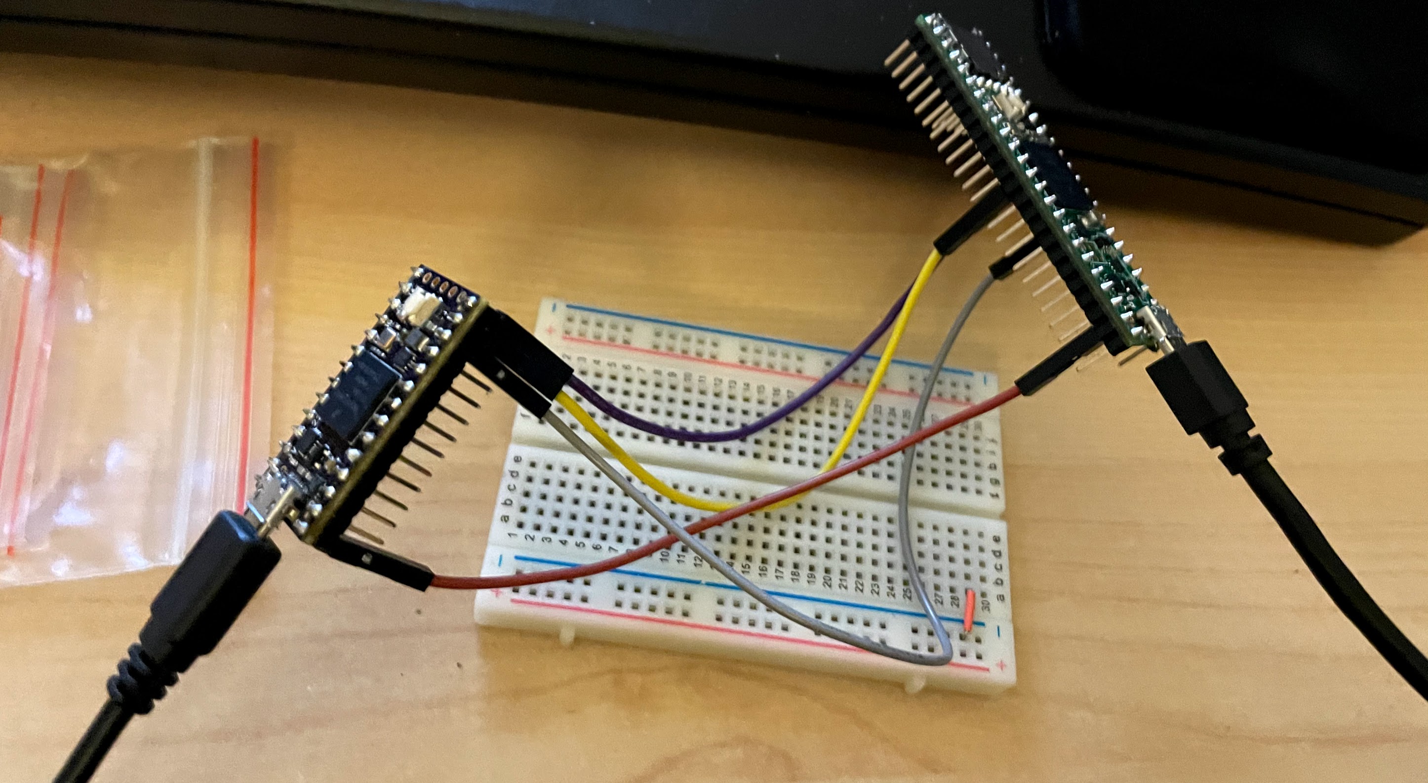
<p>If you have an un-soldered micro controller you want to measure, setup is easy:
just connect all GPIOs to the Teensy 4.0 latency test driver directly! I’m using
this for the <code>kint36</code> and <code>kint41</code>:</p>


<a href="https://michael.stapelberg.ch/posts/2021-05-08-keyboard-input-latency-qmk-kinesis/kint41_gpio_measure.jpg"><img
  srcset="https://michael.stapelberg.ch/posts/2021-05-08-keyboard-input-latency-qmk-kinesis/kint41_gpio_measure_hu_d492c4d9eba70934.jpg 2x,https://michael.stapelberg.ch/posts/2021-05-08-keyboard-input-latency-qmk-kinesis/kint41_gpio_measure_hu_c2929761c2bda740.jpg 3x"
  src="https://michael.stapelberg.ch/posts/2021-05-08-keyboard-input-latency-qmk-kinesis/kint41_gpio_measure_hu_ab2eea349c9b76db.jpg"
  alt="GPIO measurement" title="GPIO measurement"
  width="600"
  height="329"
  style="

border: 1px solid #000;

"
  
  loading="lazy"></a>


<p>(build in <code>/home/michael/kinx/kintpp/rebased</code>, last results in <code>screenlog-kint36-eager-caps.0</code>)</p>
<h3 id="kint2pp-5v">kint2pp: 5V</h3>
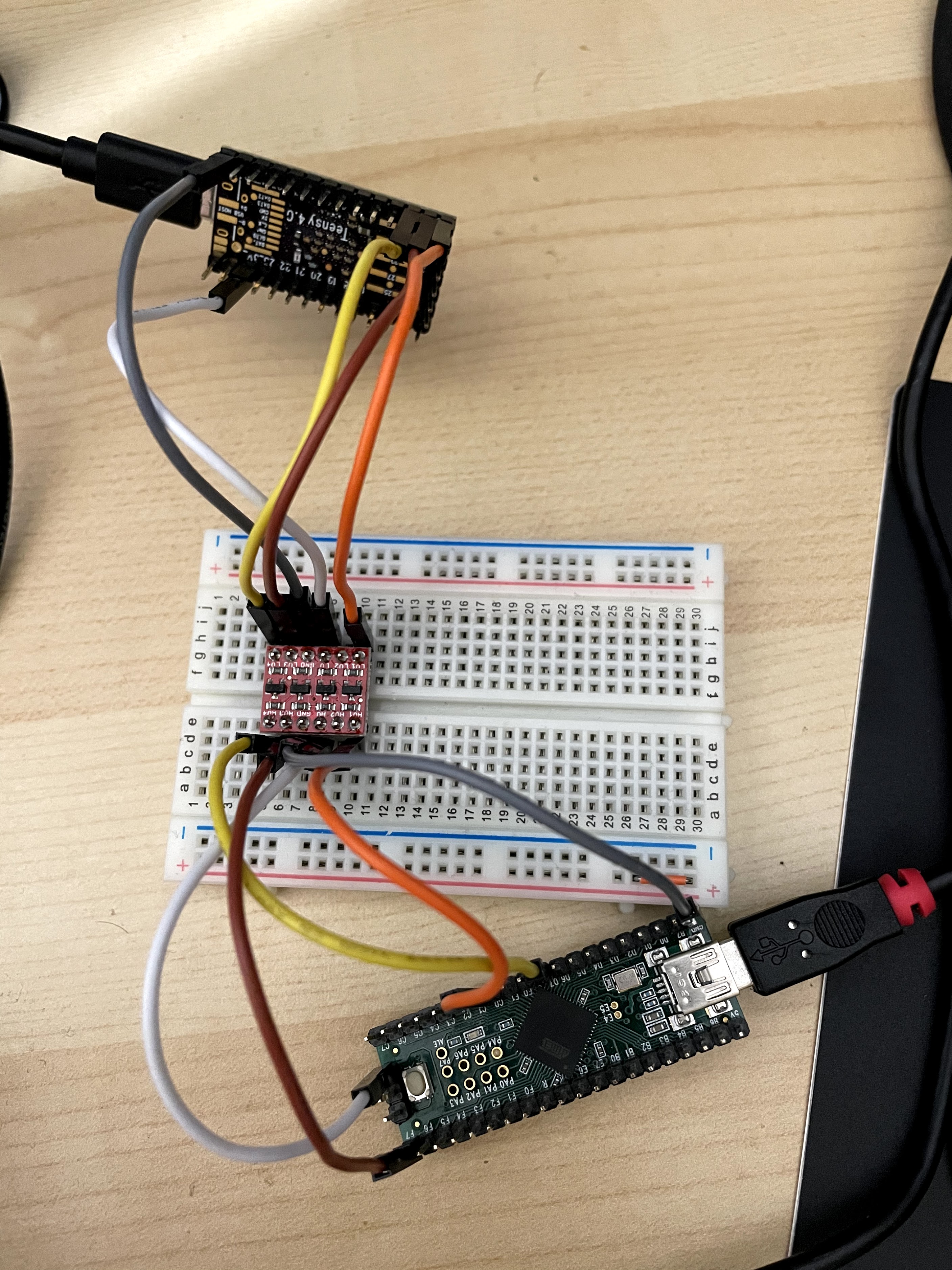
<p>Because the Teensy++ uses 5V logic levels, we need to convert the levels from/to
3.3V. This is easily done using e.g. the <a href="https://www.sparkfun.com/products/12009">SparkFun Logic Level Converter
(Bi-Directional)</a> on a breadboard:</p>


<a href="https://michael.stapelberg.ch/posts/2021-05-08-keyboard-input-latency-qmk-kinesis/kint2pp_levelshifter.jpg"><img
  srcset="https://michael.stapelberg.ch/posts/2021-05-08-keyboard-input-latency-qmk-kinesis/kint2pp_levelshifter_hu_12a9b498accee6b3.jpg 2x,https://michael.stapelberg.ch/posts/2021-05-08-keyboard-input-latency-qmk-kinesis/kint2pp_levelshifter_hu_1586d84e3749e68a.jpg 3x"
  src="https://michael.stapelberg.ch/posts/2021-05-08-keyboard-input-latency-qmk-kinesis/kint2pp_levelshifter_hu_29f44b9ec906300b.jpg"
  alt="kint2pp with level shifter" title="kint2pp with level shifter"
  width="600"
  height="800"
  style="

border: 1px solid #000;

"
  
  loading="lazy"></a>


<h3 id="kinx-fpc">kinX: FPC</h3>
<p>But what if you have a design where the micro controller doesn’t come
standalone, only soldered to a keyboard controller board, such as my earlier
kinX controller?</p>
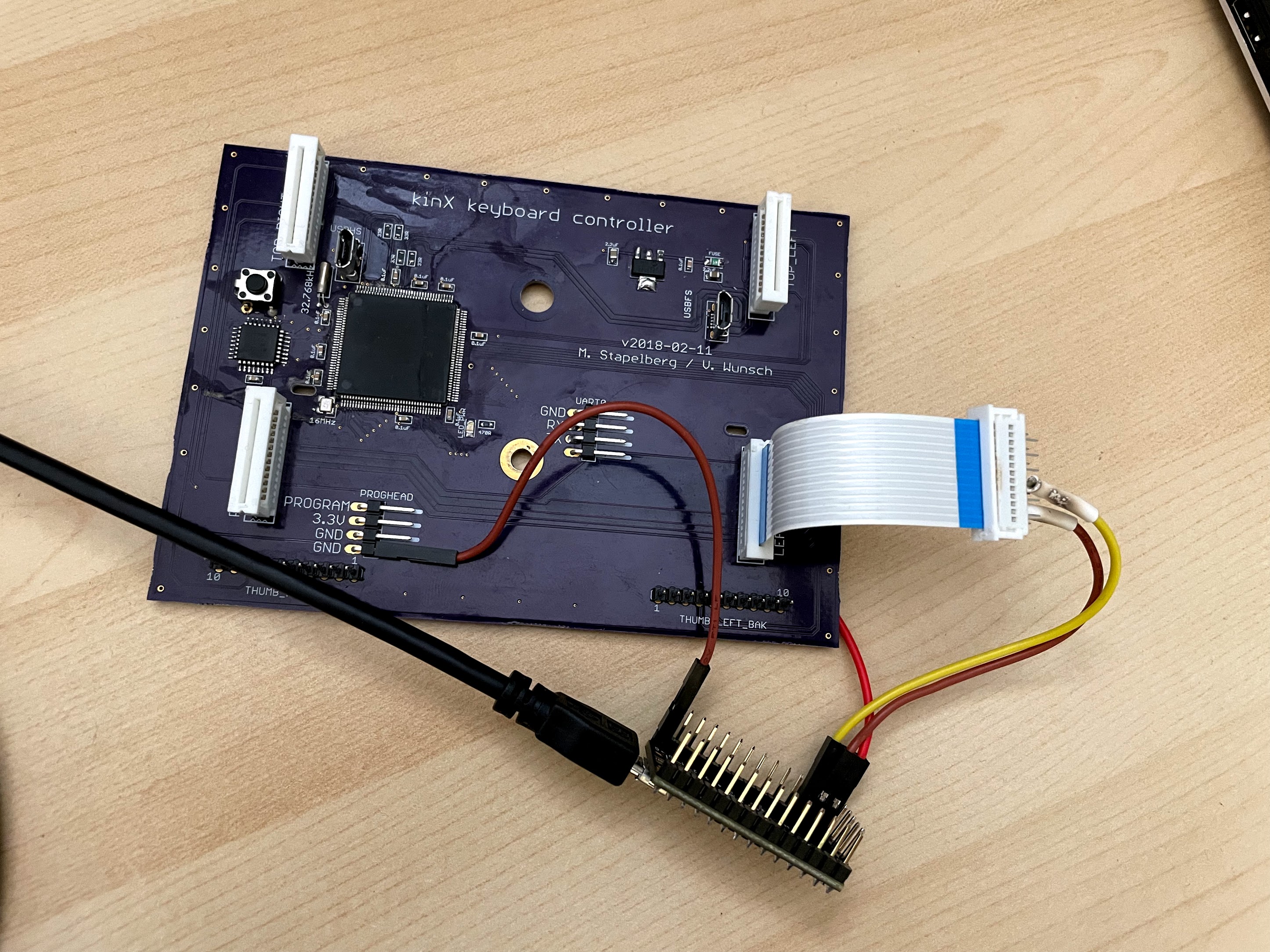
<p>You can use a spare FPC connector (<a href="https://octopart.com/39-53-2135-molex-7670149?r=sp">Molex
39-53-2135</a>) and solder
jumper wires to the pins for <code>COL_2</code> and <code>ROW_EQL</code>. For Caps Lock and Ground,
I soldered jumper wires to the board:</p>


<a href="https://michael.stapelberg.ch/posts/2021-05-08-keyboard-input-latency-qmk-kinesis/kinx_fpc_measure.jpg"><img
  srcset="https://michael.stapelberg.ch/posts/2021-05-08-keyboard-input-latency-qmk-kinesis/kinx_fpc_measure_hu_303b97bc21495308.jpg 2x,https://michael.stapelberg.ch/posts/2021-05-08-keyboard-input-latency-qmk-kinesis/kinx_fpc_measure_hu_a7c3d0af378156e0.jpg 3x"
  src="https://michael.stapelberg.ch/posts/2021-05-08-keyboard-input-latency-qmk-kinesis/kinx_fpc_measure_hu_fb0df42b0cbfcebf.jpg"
  alt="kinX measurement" title="kinX measurement"
  width="600"
  height="450"
  style="

border: 1px solid #000;

"
  
  loading="lazy"></a>


<aside class="admonition note">
  <div class="note-container">
    <div class="note-icon" style="width: 20px; height: 20px">
      <svg id="exclamation-icon" width="100%" height="100%" viewBox="0 0 24 24" version="1.1" xmlns="http://www.w3.org/2000/svg" xmlns:xlink="http://www.w3.org/1999/xlink" xml:space="preserve" style="fill-rule:evenodd;clip-rule:evenodd;stroke-linejoin:round;stroke-miterlimit:1.41421;">
    <path d="M0,0L24,0L24,24L0,24L0,0Z" style="fill:none;"/>
    <g transform="matrix(1.2,0,0,1.2,-2.4,-2.4)">
        <path d="M12,2C6.48,2 2,6.48 2,12C2,17.52 6.48,22 12,22C17.52,22 22,17.52 22,12C22,6.48 17.52,2 12,2ZM13,17L11,17L11,15L13,15L13,17ZM13,13L11,13L11,7L13,7L13,13Z" style="fill-rule:nonzero;"/>
    </g>
</svg>

    </div>
    <div class="admonition-content"><strong>Note:</strong> The
<a href="https://github.com/kinx-project/adapter-use-kb600-with-kb500-controller">adapter-use-kb600-with-kb500-controller</a>
unfortunately cannot be used for this purpose: the required pins are connected
to the ground plane.</div>
  </div>
</aside>

<h3 id="original-kinesis-controller">Original Kinesis controller</h3>
<p>But what if you don’t want to solder jumper wires directly to the board?</p>
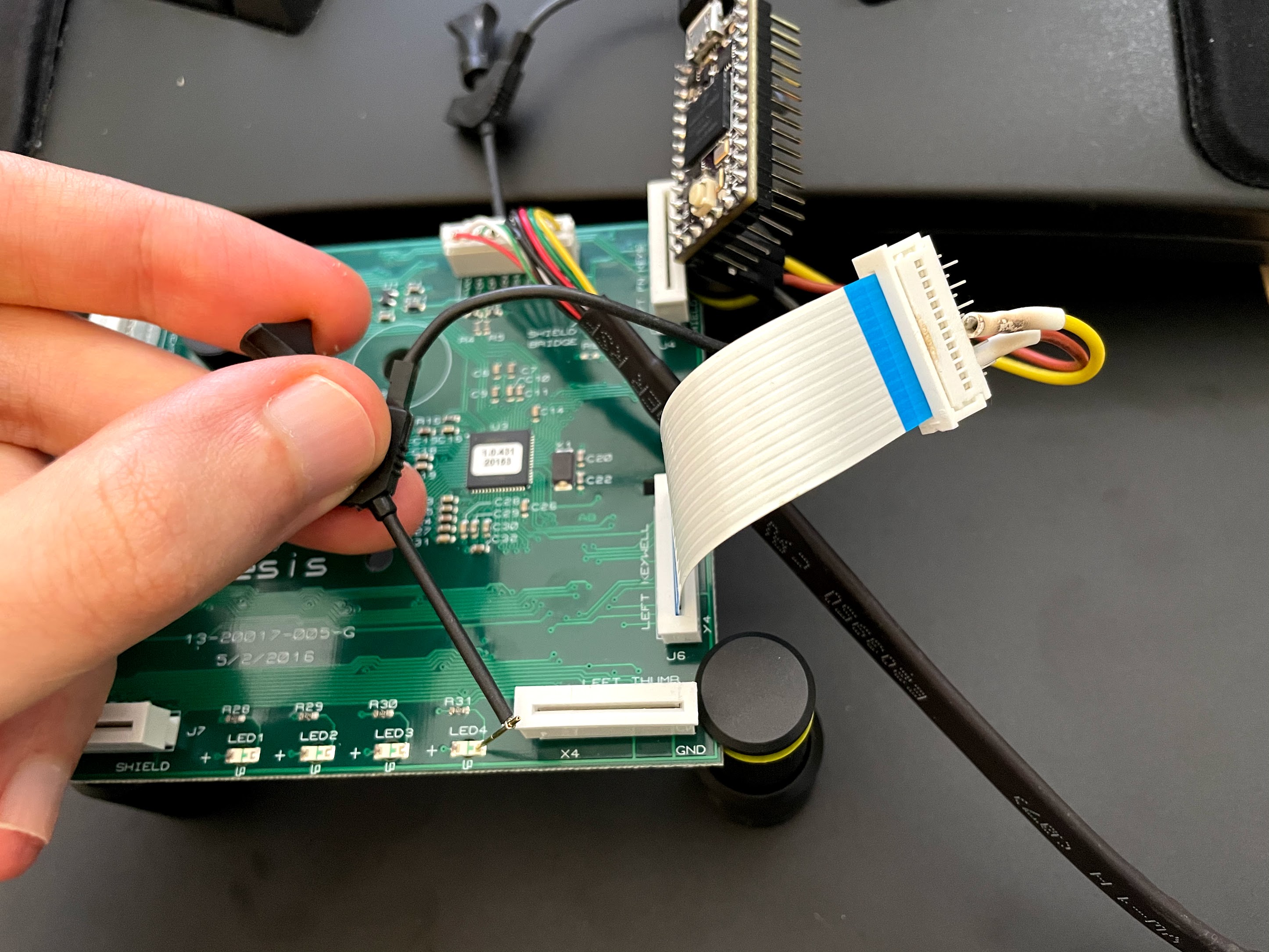
<p>The least invasive method is to connect the FPC connector break-out, and hold
probe heads onto the contacts while doing your measurements:</p>


<a href="https://michael.stapelberg.ch/posts/2021-05-08-keyboard-input-latency-qmk-kinesis/kinesis_original_measure.jpg"><img
  srcset="https://michael.stapelberg.ch/posts/2021-05-08-keyboard-input-latency-qmk-kinesis/kinesis_original_measure_hu_45aeba2fde3e969b.jpg 2x,https://michael.stapelberg.ch/posts/2021-05-08-keyboard-input-latency-qmk-kinesis/kinesis_original_measure_hu_b0f6d4ae2cca569b.jpg 3x"
  src="https://michael.stapelberg.ch/posts/2021-05-08-keyboard-input-latency-qmk-kinesis/kinesis_original_measure_hu_a709f4251f69c400.jpg"
  alt="kinesis original controller measurement" title="kinesis original controller measurement"
  width="600"
  height="450"
  style="

border: 1px solid #000;

"
  
  loading="lazy"></a>


<h2 id="qmk-input-latency">QMK input latency</h2>
<p>Now that the measurement hardware is set up, we can go through the code.</p>
<p>The following sections each cover one possible contributor to input latency.</p>
<h3 id="eagerdebounce">Eager debounce</h3>
<p>Key switches don’t generate a clean signal when pressed, instead they show a
ripple effect. Getting rid of this ripple is called
<a href="https://en.wiktionary.org/wiki/debounce">debouncing</a>, and every keyboard
firmware does it.</p>
<p>See <a href="https://docs.qmk.fm/#/feature_debounce_type">QMK’s documentation on the Debounce
API</a> for a good explanation of the
differences between the different debounce approaches.</p>
<p>QMK’s default debounce algorithm <code>sym_defer_g</code> is chosen very cautiously. I
don’t know what the criteria are specifically for which types of key switches
suffer from noise and therefore need the <code>sym_defer_g</code> algorithm, but I know
that Cherry MX key switches with diodes like used in the Kinesis Advantage don’t
have noise and hence can use the other debounce algorithms, too.</p>
<p>While the default <code>sym_defer_g</code> debounce algorithm is robust, it also adds 5ms
of input latency:</p>
<pre tabindex="0"><code>% benchstat screenlog-kint36.0
name                 time/op
KeypressToLEDReport  7.61ms ± 8%
</code></pre><p>For lower input latency, we need an <code>eager</code> algorithm. Specifically, I am
chosing the <code>sym_eager_pk</code> debounce algorithm by adding to my
<code>keyboards/kinesis/kint36/rules.mk</code>:</p>
<pre tabindex="0"><code>DEBOUNCE_TYPE = sym_eager_pk
</code></pre><p>Now, the extra 5ms are gone:</p>
<pre tabindex="0"><code>% benchstat screenlog-kint36-eager.0
name                 time/op
KeypressToLEDReport  2.12ms ±16%
</code></pre><p>Example change: <a href="https://github.com/qmk/qmk_firmware/pull/12626">https://github.com/qmk/qmk_firmware/pull/12626</a></p>
<h3 id="quickusbpolling">Quicker USB polling interval</h3>
<p>The USB host (computer) divides time into fixed-length segments called frames:</p>
<ul>
<li>USB Full Speed (USB 1.0) uses frames that are 1ms each.</li>
<li>USB High Speed (USB 2.0) introduces micro frames, which are 125μs.</li>
</ul>
<p>Each USB device specifies in its device descriptor how frequently (in frames)
the device should be polled. The <a href="https://en.wikipedia.org/wiki/USB_(Communications)#Transaction_latency">quickest polling
rate</a>
for USB 1.0 is 1 frame, meaning the device can send data after at most
1ms. Similarly, for USB 2.0, it’s 1 micro frame, i.e. send data every 125μs.</p>
<p>Of course, a quicker polling rate also means occupying resources on the USB bus
which are then no longer available to other devices. On larger USB hubs, this
might mean fewer devices can be used concurrently. The specifics of this
limitation depend on a lot of other factors, too. The polling rate plays a role,
in combination with the max. packet size and the number of endpoints.</p>
<p>Note that we are only talking about concurrent device usage, not about hogging
bandwidth: the bulk transfers that USB mass storage devices use are not any
slower in my tests. I achieve about 37 MiB/s with or without the kint41 USB 2.0
High Speed controller with <code>bInterval=1</code> present.</p>
<p>Even connecting two kint41 controllers at the same time still leaves enough
resources to use a Logitech C920 webcam in its most bandwidth-intensive pixel
format and resolution. The same cannot be said for e.g. NXP’s LPC-Link2 debug
probe.</p>
<aside class="admonition note">
  <div class="note-container">
    <div class="note-icon" style="width: 20px; height: 20px">
      <svg id="exclamation-icon" width="100%" height="100%" viewBox="0 0 24 24" version="1.1" xmlns="http://www.w3.org/2000/svg" xmlns:xlink="http://www.w3.org/1999/xlink" xml:space="preserve" style="fill-rule:evenodd;clip-rule:evenodd;stroke-linejoin:round;stroke-miterlimit:1.41421;">
    <path d="M0,0L24,0L24,24L0,24L0,0Z" style="fill:none;"/>
    <g transform="matrix(1.2,0,0,1.2,-2.4,-2.4)">
        <path d="M12,2C6.48,2 2,6.48 2,12C2,17.52 6.48,22 12,22C17.52,22 22,17.52 22,12C22,6.48 17.52,2 12,2ZM13,17L11,17L11,15L13,15L13,17ZM13,13L11,13L11,7L13,7L13,13Z" style="fill-rule:nonzero;"/>
    </g>
</svg>

    </div>
    <div class="admonition-content"><strong>Open question:</strong> Would declaring multiple alternate settings in our USB device
descriptor dynamically reduce resource usage? Our keyboard could offer one
alternate setting with <code>bInterval=1</code> and one with <code>bInterval=10</code>.</div>
  </div>
</aside>

<p>To display the configured interval, the Linux kernel provides a debug pseudo file:</p>
<pre tabindex="0"><code>% sudo cat /sys/kernel/debug/usb/devices

[…]
T:  Bus=01 Lev=02 Prnt=09 Port=02 Cnt=02 Dev#= 53 Spd=480  MxCh= 0
D:  Ver= 2.00 Cls=00(&gt;ifc ) Sub=00 Prot=00 MxPS=64 #Cfgs=  1
P:  Vendor=1209 ProdID=345c Rev= 0.01
S:  Manufacturer=&#34;https://github.com/stapelberg&#34;
S:  Product=&#34;kinT (kint41)&#34;
C:* #Ifs= 3 Cfg#= 1 Atr=a0 MxPwr=500mA
I:* If#= 0 Alt= 0 #EPs= 1 Cls=03(HID  ) Sub=01 Prot=01 Driver=usbhid
E:  Ad=81(I) Atr=03(Int.) MxPS=   8 Ivl=125us
I:* If#= 1 Alt= 0 #EPs= 1 Cls=03(HID  ) Sub=00 Prot=00 Driver=usbhid
E:  Ad=82(I) Atr=03(Int.) MxPS=  32 Ivl=125us
I:* If#= 2 Alt= 0 #EPs= 2 Cls=03(HID  ) Sub=00 Prot=00 Driver=usbhid
E:  Ad=83(I) Atr=03(Int.) MxPS=  32 Ivl=125us
E:  Ad=04(O) Atr=03(Int.) MxPS=  32 Ivl=125us
[…]
</code></pre><p>Alternatively, you can display the USB device descriptor using e.g. <code>sudo lsusb -v -d 1209:345c</code> and interpret the <code>bInterval</code> setting yourself.</p>
<p>The above shows the best case: a USB 2.0 High Speed device (<code>Spd=480</code>) with
<code>bInterval=1</code> in its device descriptor (<code>Iv=125us</code>).</p>
<p>The original Kinesis Advantage 2 keyboard controller (KB600) uses USB 2.0, but
in Full Speed mode (<code>Spd=12</code>), i.e. no faster than USB 1.1. In addition, they
specify <code>bInterval=10</code>, which results in a 10ms polling interval (<code>Ivl=10ms</code>):</p>
<pre tabindex="0"><code>T:  Bus=01 Lev=02 Prnt=09 Port=02 Cnt=02 Dev#= 52 Spd=12   MxCh= 0
D:  Ver= 2.00 Cls=00(&gt;ifc ) Sub=00 Prot=00 MxPS=64 #Cfgs=  1
P:  Vendor=29ea ProdID=0102 Rev= 1.00
S:  Manufacturer=Kinesis
S:  Product=Advantage2 Keyboard
C:* #Ifs= 3 Cfg#= 1 Atr=a0 MxPwr=100mA
I:* If#= 0 Alt= 0 #EPs= 1 Cls=03(HID  ) Sub=01 Prot=02 Driver=usbhid
E:  Ad=83(I) Atr=03(Int.) MxPS=   8 Ivl=10ms
I:* If#= 1 Alt= 0 #EPs= 1 Cls=03(HID  ) Sub=01 Prot=01 Driver=usbhid
E:  Ad=84(I) Atr=03(Int.) MxPS=   8 Ivl=2ms
I:* If#= 2 Alt= 0 #EPs= 1 Cls=03(HID  ) Sub=00 Prot=00 Driver=usbhid
E:  Ad=85(I) Atr=03(Int.) MxPS=   8 Ivl=2ms
</code></pre><p>My recommendation:</p>
<ul>
<li>With USB 1.1 Full Speed, definitely specify <code>bInterval=1</code>. I’m not aware of
any downsides.</li>
<li>With USB 2.0 High Speed, I also think <code>bInterval=1</code> is a good choice, but I am
less certain. If you run into trouble, reduce to <code>bInterval=3</code> and send me a
message :)</li>
</ul>
<p>For details on measuring, see <a href="#appendixb">Appendix B: USB polling interval (device
side)</a>.</p>
<p>Example change: <a href="https://github.com/qmk/qmk_firmware/pull/12625">https://github.com/qmk/qmk_firmware/pull/12625</a></p>
<h3 id="fastmatrixscan">Faster matrix scan</h3>
<p>The purpose of a keyboard controller is reporting pressed keys after scanning
the key matrix. The more scans a keyboard controller can do per second, the
faster it can react to your key press.</p>
<p>How many scans your controller does depends on multiple factors:</p>
<ul>
<li>
<p>The clock speed of your micro controller. It’s worth checking if your micro
controller model supports running at faster clock speeds, or upgrading your
keyboard to a faster model to begin with. There is a point of diminishing
returns, which I would guess is at ≈100 MHz. Comparing e.g. the kint36 at 120
MHz vs. 180 MHz, the difference in scan-to-scan is 5μs.</p>
</li>
<li>
<p>How much other code your firmware runs aside from matrix scanning. If you
enable any non-standard QMK features, or even self-written code, it’s worth
disabling and measuring.</p>
</li>
<li>
<p>Whether you run scans back-to-back or e.g. synchronized with USB
start-of-frame interrupts. QMK runs scans back-to-back, so this point is only
relevant for other firmwares.</p>
</li>
<li>
<p>How long you need to sleep to let the signal settle. Reducing your sleep times
results in more scans per second, but if you don’t sleep long enough, you’ll
see ghost key presses. See also the next section about Shorter sleeps.</p>
</li>
</ul>
<p>For details on measuring, see the <a href="#scantoscandelay">Scan-to-scan delay section</a>
above.</p>
<p>I also tried configuring the GPIOs to be faster to see if that would reduce the
required unselect delay, but unfortunately there was no difference between the
default setting and the fastest setting: drive strength 6 (<code>DSE=6</code>), fast
slew rate (<code>SRE=1</code>), 200 MHz (<code>SPEED=3</code>).</p>
<h3 id="shortsleeps">Shorter sleeps</h3>
<p>QMK calls <a href="https://www.chibios.org/dokuwiki/doku.php?id=chibios:documentation:books:rt:kernel_threading#delays_api">ChibiOS’s <code>chThdSleepMicroseconds</code>
function</a>
in its matrix scanning code. This function unfortunately has a rather long
shortest sleep duration of 1 ChibiOS tick: if you tell it to sleep less than
100μs, it will still sleep at least 100μs!</p>
<p>This is a problem on controllers such as the kint41, where we want to sleep for
only 10μs.</p>
<p>The length of a ChibiOS tick is determined by how the ARM SysTick timer is set
up on the specific micro controller you’re using. While the SysTick timer itself
could be configured to fire more frequently, it is not advisable to shorten
ChibiOS ticks: <code>chSysTimerHandlerI()</code> <a href="http://forum.chibios.org/viewtopic.php?t=3712#p27851">must be executable in less than one
tick</a>.</p>
<p>Instead, I found it easier to implement short delays by busy-looping until the
ARM Cycle Counter Register (<code>CYCCNT</code>) indicates enough time has passed. Here’s
an example from <code>keyboards/kinesis/kint41/kint41.c</code>:</p>
<div class="highlight"><pre tabindex="0" style="background-color:#f0f0f0;-moz-tab-size:4;-o-tab-size:4;tab-size:4;-webkit-text-size-adjust:none;"><code class="language-c" data-lang="c"><span style="display:flex;"><span><span style="color:#60a0b0;font-style:italic">// delay_inline sleeps for |cycles| (e.g. sleeping for F_CPU will sleep 1s).
</span></span></span><span style="display:flex;"><span><span style="color:#60a0b0;font-style:italic">//
</span></span></span><span style="display:flex;"><span><span style="color:#60a0b0;font-style:italic">// delay_inline assumes the cycle counter has already been initialized and
</span></span></span><span style="display:flex;"><span><span style="color:#60a0b0;font-style:italic">// should not be modified, i.e. is safe to call during keyboard matrix scan.
</span></span></span><span style="display:flex;"><span><span style="color:#60a0b0;font-style:italic">//
</span></span></span><span style="display:flex;"><span><span style="color:#60a0b0;font-style:italic">// ChibiOS enables the cycle counter in chcore_v7m.c.
</span></span></span><span style="display:flex;"><span><span style="color:#007020;font-weight:bold">static</span> <span style="color:#902000">void</span> <span style="color:#06287e">delay_inline</span>(<span style="color:#007020;font-weight:bold">const</span> <span style="color:#902000">uint32_t</span> cycles) {
</span></span><span style="display:flex;"><span>  <span style="color:#007020;font-weight:bold">const</span> <span style="color:#902000">uint32_t</span> start <span style="color:#666">=</span> DWT<span style="color:#666">-&gt;</span>CYCCNT;
</span></span><span style="display:flex;"><span>  <span style="color:#007020;font-weight:bold">while</span> ((DWT<span style="color:#666">-&gt;</span>CYCCNT <span style="color:#666">-</span> start) <span style="color:#666">&lt;</span> cycles) {
</span></span><span style="display:flex;"><span>    <span style="color:#60a0b0;font-style:italic">// busy-loop until time has passed
</span></span></span><span style="display:flex;"><span>  }
</span></span><span style="display:flex;"><span>}
</span></span><span style="display:flex;"><span>
</span></span><span style="display:flex;"><span><span style="color:#902000">void</span> <span style="color:#06287e">matrix_output_unselect_delay</span>(<span style="color:#902000">void</span>) {
</span></span><span style="display:flex;"><span>  <span style="color:#60a0b0;font-style:italic">// 600 cycles at 0.6 cycles/ns == 1μs
</span></span></span><span style="display:flex;"><span>  <span style="color:#007020;font-weight:bold">const</span> <span style="color:#902000">uint32_t</span> cycles_per_us <span style="color:#666">=</span> <span style="color:#40a070">600</span>;
</span></span><span style="display:flex;"><span>  <span style="color:#06287e">delay_inline</span>(<span style="color:#40a070">10</span> <span style="color:#666">*</span> cycles_per_us);
</span></span><span style="display:flex;"><span>}
</span></span></code></pre></div><p>Of course, the cycles/ns value is specific to the frequency at which your micro
controller runs, so this code needs to be adjusted for each platform.</p>
<h2 id="results">Results</h2>
<p>With the QMK keyboard firmware configured for lowest input latency, how do the
different Kinesis keyboard controller compare? Here are my measurements:</p>
<table>
	<thead>
			<tr>
					<th>model</th>
					<th>CPU speed</th>
					<th>USB poll interval</th>
					<th>scan-to-scan</th>
					<th>scan rate</th>
					<th>caps-to-report</th>
			</tr>
	</thead>
	<tbody>
			<tr>
					<td>kint41</td>
					<td>600 MHz</td>
					<td>125μs</td>
					<td>181μs</td>
					<td>5456 scans/s</td>
					<td>930µs ±17%</td>
			</tr>
			<tr>
					<td>kinX</td>
					<td>120 MHz</td>
					<td>125μs</td>
					<td>213μs</td>
					<td>4694 scans/s</td>
					<td>953µs ±15%</td>
			</tr>
			<tr>
					<td>kint36</td>
					<td>180 MHz</td>
					<td>1000μs</td>
					<td>444μs</td>
					<td>2252 scans/s</td>
					<td>1.97ms ±15%</td>
			</tr>
			<tr>
					<td>kint2pp</td>
					<td>16 MHz</td>
					<td>1000μs</td>
					<td>926μs</td>
					<td>1078 scans/s</td>
					<td>3.27ms ±32%</td>
			</tr>
			<tr>
					<td>original</td>
					<td>60 MHz</td>
					<td>10000μs</td>
					<td>1936μs</td>
					<td>516 scans/s</td>
					<td>13.6ms ±21%</td>
			</tr>
	</tbody>
</table>
<p>The changes required to obtain these results are included since QMK 0.12.38
(2021-04-20).</p>
<p><a href="https://github.com/kinx-project/kint/issues/5">kint41 support is being added</a>
with all required changes to begin with, but still in progress.</p>
<p>The following sections go into detail about the results.</p>
<h3 id="kint41">kint41</h3>
<p>I am glad that the most recent Teensy 4.1 micro controller takes the lead! The
kinX controller achieved similar numbers, but was quite difficult to build, so
few people ended up using it.</p>
<p>The key improvement compared to the Teensy 3.6 is the now-available USB 2.0 High
Speed, and the powerful clock speed of 600 MHz allows for an even faster matrix
scan rate.</p>
<h3 id="kinx">kinX</h3>
<p>In my <a href="/posts/2018-04-17-kinx-keyboard-controller/">previous article about the kinX
controller</a>, I measured the kinX
scan delay as ≈100μs. During my work on this article, I learnt that the ≈100μs
figure was misleading: the measurement code turned off interrupts to measure
only the scan function. While that is technically correct, it is not a useful
measure, as in practice, <a href="https://github.com/kinx-project/mk66f-fw/commit/cae21f3d13331061bcd8c9d411adbb0d7d8c0ae4">interrupts should not be
disabled</a>,
and the scanning function is interrupted frequently enough that it comes in at
≈208μs.</p>
<p>I also fixed the USB polling interval in the kinX firmware, which <a href="https://github.com/kinx-project/mk66f-fw/commit/b40ae0287ed3b042886e29621dbeecefba1c148b">wasn’t set to
<code>bInterval=1</code></a>.</p>
<h3 id="original-kinesis">Original Kinesis</h3>
<p>The original keyboard controller that the Kinesis Advantage 2 (KB600) keyboard
comes with uses <a href="https://www.microchip.com/wwwproducts/en/AT32UC3B0256#datasheet-toggle">an AT32UC3B0256 micro
controller</a>
which is clocked at 60 MHz, but the measured input latency is much higher than
even the slowest kint controller (kint2pp at 16 MHz). What gives?</p>
<p>Here’s what we can deduce without access to their firmware:</p>
<ol>
<li>They seem to be using an <a href="#eagerdebounce">eager debounce algorithm</a> (good!),
otherwise we would observe even higher latency.</li>
<li>Their <a href="#quickusbpolling">USB polling interval</a> setting (<code>bInterval=10</code>) is
excessively high, even more so because they are using USB Full Speed with
longer USB frames. I would recommend they change it to <code>bInterval=1</code> for up
to 10ms less input latency!</li>
<li>The matrix scan rate is twice as slow as with my kint2pp. I can’t say for
sure why this is. Perhaps their firmware does a lot of other things between
matrix scans.</li>
</ol>
<p>Note that we could not apply the <a href="#eagercaps">Eager Caps Lock LED</a> firmware
change to the original controller, which is why the measurement variance is
±21%. This variance includes ± 1.9ms for finishing a matrix scan before updating
the LED state.</p>
<h2 id="conclusion">Conclusion</h2>
<p>After analyzing the different controllers in my measurement environment, I think
the following factors play the largest role in keyboard input latency, ordered
by importance:</p>
<ol>
<li>Does the firmware use an <a href="#eagerdebounce">eager debounce algorithm</a>?</li>
<li>Does the device specify a <a href="#quickusbpolling">quick USB polling rate (<code>bInterval</code>
setting)</a>?</li>
<li>Is the matrix scan frequency in the expected range, or are there unexpected
slow-downs?</li>
</ol>
<p>Hopefully, this article gives you all the tools you need to measure and reduce
keyboard input latency of your own keyboard controller!</p>
<h2 id="appendix-a-isitsnappy">Appendix A: isitsnappy</h2>
<p>The iPhone app <a href="https://isitsnappy.com/">Is It Snappy?</a> records video using the
iPhone’s 240 fps camera and allows you to mark the frame that starts
respectively ends the measurement.</p>
<p>The app does a good job of making this otherwise tedious process of navigating a
video frame by frame much more pleasant.</p>
<p>However, for measuring keyboard input latency, I think this approach is futile:</p>
<ul>
<li>The resolution is too imprecise. At 240 fps, that means each frame represents
4.6ms of time, which is already higher than the input latency of our slowest
micro controller.</li>
<li>Visually deciding whether a key switch is pressed or not pressed, at
frame-perfect precision, seems impossible to me.</li>
</ul>
<p>I believe the app can work, provided the latency you want to measure is really
high. But with the devices covered in this article, the app couldn’t measure
even 10ms of injected input latency.</p>
<h2 id="appendixb">Appendix B: USB polling interval (device side)</h2>
<p>You can also verify the USB polling interval on the device side. In the SOF
(Start Of Frame) interrupt in <code>tmk_core/protocol/chibios/usb_main.c</code>, we can
print the cycle delta to the previous SOF callback, every second:</p>
<div class="highlight"><pre tabindex="0" style="background-color:#f0f0f0;-moz-tab-size:4;-o-tab-size:4;tab-size:4;-webkit-text-size-adjust:none;"><code class="language-c" data-lang="c"><span style="display:flex;"><span><span style="color:#007020">#include</span> <span style="color:#007020">&#34;timer.h&#34;</span><span style="color:#007020">
</span></span></span><span style="display:flex;"><span>
</span></span><span style="display:flex;"><span><span style="color:#007020;font-weight:bold">static</span> <span style="color:#902000">uint32_t</span> last_sof <span style="color:#666">=</span> <span style="color:#40a070">0</span>;
</span></span><span style="display:flex;"><span><span style="color:#007020;font-weight:bold">static</span> <span style="color:#902000">uint32_t</span> sof_timer <span style="color:#666">=</span> <span style="color:#40a070">0</span>;
</span></span><span style="display:flex;"><span><span style="color:#902000">void</span> <span style="color:#06287e">kbd_sof_cb</span>(USBDriver <span style="color:#666">*</span>usbp) {
</span></span><span style="display:flex;"><span>  (<span style="color:#902000">void</span>)usbp;
</span></span><span style="display:flex;"><span>
</span></span><span style="display:flex;"><span>  <span style="color:#902000">uint32_t</span> now <span style="color:#666">=</span> DWT<span style="color:#666">-&gt;</span>CYCCNT;
</span></span><span style="display:flex;"><span>  <span style="color:#902000">uint32_t</span> delta <span style="color:#666">=</span> now <span style="color:#666">-</span> last_sof;
</span></span><span style="display:flex;"><span>  last_sof <span style="color:#666">=</span> now;
</span></span><span style="display:flex;"><span>
</span></span><span style="display:flex;"><span>  <span style="color:#902000">uint32_t</span> timer_now <span style="color:#666">=</span> <span style="color:#06287e">timer_read32</span>();
</span></span><span style="display:flex;"><span>  <span style="color:#007020;font-weight:bold">if</span> (<span style="color:#06287e">TIMER_DIFF_32</span>(timer_now, sof_timer) <span style="color:#666">&gt;</span> <span style="color:#40a070">1000</span>) {
</span></span><span style="display:flex;"><span>    sof_timer <span style="color:#666">=</span> timer_now;
</span></span><span style="display:flex;"><span>    <span style="color:#06287e">dprintf</span>(<span style="color:#4070a0">&#34;sof delta: %u cycles&#34;</span>, delta);
</span></span><span style="display:flex;"><span>  }
</span></span><span style="display:flex;"><span>}
</span></span></code></pre></div><p>Using <code>hid_listen</code>, we expect to see ≈75000 cycles of delta, which
corresponds to the 125μs microframe latency of USB 2.0 High Speed with
<code>bInterval=1</code> in the USB device descriptor:</p>
<p>125μs * 1000 * 0.6 cycles/ns = 75000 cycles</p>
]]></content>
  </entry>
  <entry>
    <title type="html"><![CDATA[Introducing the kinT kinesis keyboard controller]]></title>
    <link href="https://michael.stapelberg.ch/posts/2020-07-09-kint-kinesis-keyboard-controller/"/>
    <id>https://michael.stapelberg.ch/posts/2020-07-09-kint-kinesis-keyboard-controller/</id>
    <published>2020-07-09T09:25:00+02:00</published>
    <content type="html"><![CDATA[<p><a href="../../Bilder/2020-05-22-desk-setup-kinesis.jpg"><img
src="../../Bilder/2020-05-22-desk-setup-kinesis.jpg"
alt="Kinesis Advantage ergonomic keyboard"
width="200" align="right" style="border: 1px solid #ccc; margin-left: 1em"></a></p>
<p>Back <a href="../2013-03-21-kinesis_custom_controller/">in 2013, I published a replacement
controller</a> for the Kinesis Advantage
ergonomic keyboard. In the community, it is often referred to simply as the
“stapelberg”, and became quite popular.</p>
<p>Many people like to use the feature-rich <a href="https://docs.qmk.fm/">QMK firmware</a>,
which supports my replacement controller out of the box.</p>
<p><a href="../../Bilder/kinesis-pcb-mounted.jpg"><img
src="../../Bilder/kinesis-pcb-mounted.jpg"
alt="kinesis pcb mounted"
width="200" align="right" style="border: 1px solid #ccc; margin-left: 1em"></a></p>
<p>On eBay, you can frequently find complete stapelberg kits or even
already-modified Kinesis keyboards including the stapelberg board for sale.</p>
<p>In 2017, Kinesis released the Kinesis Advantage 2, which uses a different
connector (an FPC connector) for connecting the two thumb pad PCBs to the
controller PCB, instead of the soldered cable the older Kinesis Advantage
used. Aside from the change in connector and cable type, the newer keyboard uses
the same pinout as the old one.</p>
<p>I wanted to at least update my project to support the Kinesis Advantage 2. While
doing so, I decided to also make a bunch of improvements to make the project
more approachable and usable for beginners. Among many other improvements, the
project switched from Eagle to <a href="https://kicad-pcb.org/">KiCad</a>, which is FOSS
and means no more costly license fees!</p>
<h2 id="kint-t-for-teensy">kinT (T for Teensy!)</h2>
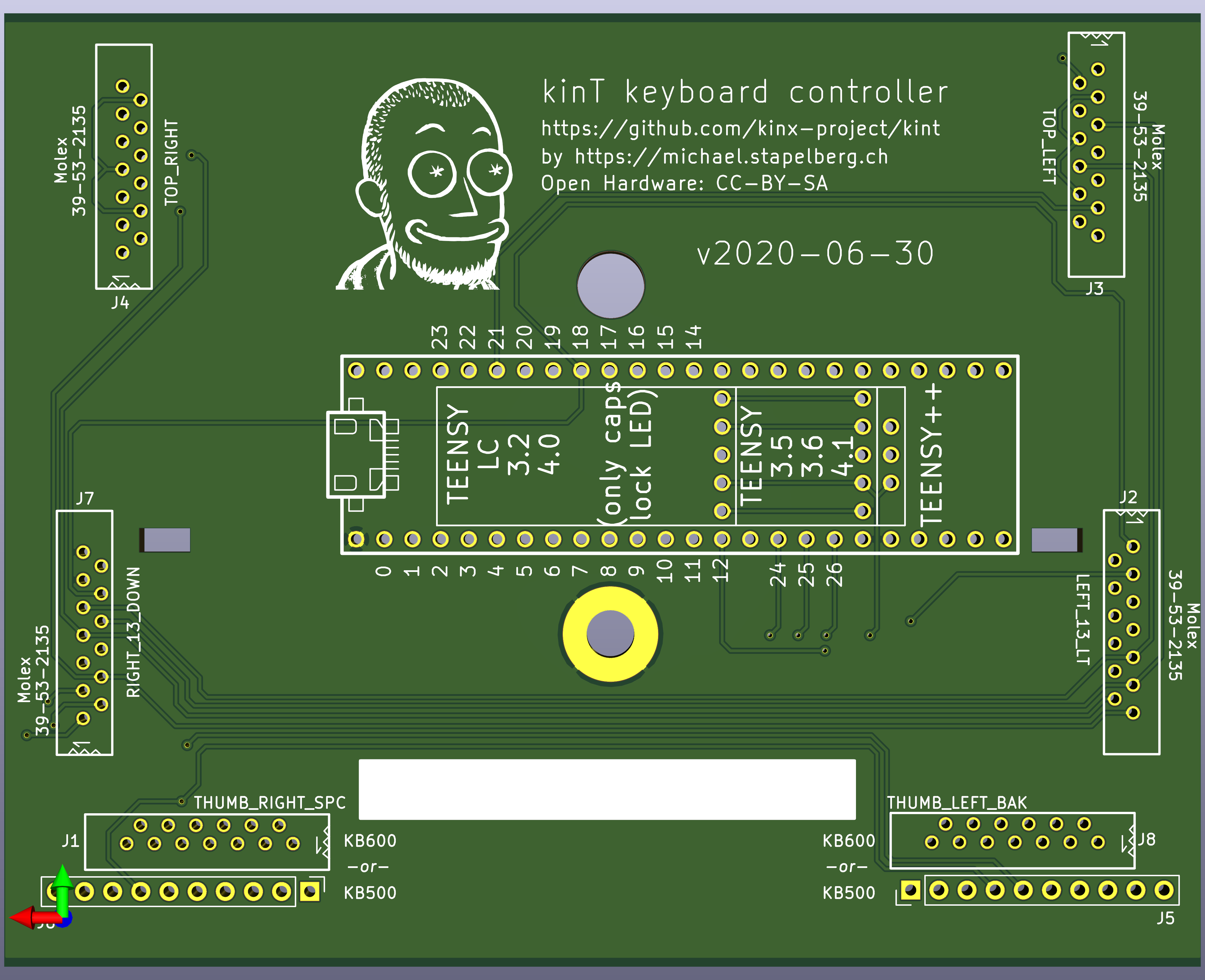
<p>I am hereby announcing the <a href="https://github.com/kinx-project/kint">kinT kinesis keyboard
controller</a>: a replacement keyboard
controller for your Kinesis Advantage or Advantage 2 ergonomic keyboards.</p>


<a href="https://michael.stapelberg.ch/posts/2020-07-09-kint-kinesis-keyboard-controller/kint-pcb-3d-render-back-v2020-06-30.png"><img
  srcset="https://michael.stapelberg.ch/posts/2020-07-09-kint-kinesis-keyboard-controller/kint-pcb-3d-render-back-v2020-06-30_hu_ee88b3589de34c6a.png 2x,https://michael.stapelberg.ch/posts/2020-07-09-kint-kinesis-keyboard-controller/kint-pcb-3d-render-back-v2020-06-30_hu_bfc9a52354ba4c36.png 3x"
  src="https://michael.stapelberg.ch/posts/2020-07-09-kint-kinesis-keyboard-controller/kint-pcb-3d-render-back-v2020-06-30_hu_422ef5948cd1d105.png"
  alt="kinT keyboard controller" title="kinT keyboard controller"
  width="600"
  height="488"
  style="

border: 1px solid #000;

"
  
  loading="lazy"></a>


<p>The Teensy footprint looks a bit odd, but it’s a combined footprint so that you
can use the same board with many different Teensy microcontrollers, giving you
full flexibility regarding cost and features. See <a href="https://github.com/kinx-project/kint#compatibility-which-teensy-to-use">“Compatibility: which Teensy
to
use?”</a>
for more details.</p>
<hr>
<p>I <a href="../2013-03-21-kinesis_custom_controller/">originally replaced the controller of my Kinesis Advantage to work around a
bug</a>, but these days I do most of it
just because I enjoy tinkering with keyboards.</p>
<p>You might consider to replace your keyboard controller for example…</p>
<ul>
<li>to build or modify your own keyboard</li>
<li>to <a href="https://michael.stapelberg.ch/posts/2013-03-21-kinesis_custom_controller/">work around bugs in the standard controller</a></li>
<li>because you prefer to run open source software such as the <a href="https://docs.qmk.fm/">QMK firmware</a>, even on your keyboard</li>
</ul>
<h2 id="building-your-own-kint-keyboard-controller">Building your own kinT keyboard controller</h2>
<ol>
<li>
<p>Follow <a href="https://github.com/kinx-project/kint#buying-the-board-and-components-bill-of-materials">“Buying the board and components (Bill of
materials)”</a>. When
ordering from OSH Park (board) and Digi-Key (components), you’ll get the
minimum quantity of 3 boards for 72 USD (24 USD per board), and one set of
components for 49 USD.</p>
<ul>
<li>If you have any special requirements regarding which Teensy microcontroller
to use, this is the step where you would replace the Teensy 3.6 with your
choice.</li>
</ul>
</li>
<li>
<p>Wait for the components to arrive. When ordering from big shops like Digi-Key
or Mouser, this typically takes 2 days to many places in the world.</p>
</li>
<li>
<p>Wait for the boards to arrive. This takes 6 days in the best case when
ordering from OSH Park with their Super Swift Service option. In general, the
longer you are willing to wait, the cheaper it is going to get.</p>
</li>
<li>
<p>Follow <a href="https://github.com/kinx-project/kint#soldering">the soldering
guide</a>. This will take about
an hour.</p>
</li>
<li>
<p><a href="https://github.com/kinx-project/kint#installing-the-firmware">Install the firmware</a></p>
</li>
</ol>
<h2 id="improvements-over-the-older-replacement-board">Improvements over the older replacement board</h2>
<p>In case you’re familiar with the older replacement board and are wondering what
changed, here is a complete list:</p>
<ul>
<li>
<p>The kinT supports both, the older Kinesis Advantage (KB500) <strong>and</strong> the newer
Kinesis Advantage 2 (KB600) keyboards. They differ in how the thumb pads are
connected. See the soldering instructions below.</p>
</li>
<li>
<p>The kinT is made for the newer Teensy 3.x and 4.x series, which will remain
widely available for years to come, whereas <a href="https://www.pjrc.com/store/teensypp.html">the future of the Teensy++ 2.0 is
not as certain</a>.</p>
</li>
<li>
<p>The kinT is a smaller PCB (4.25 x 3.39 inches, or 108.0 x 86.1 mm), which makes it:</p>
<ul>
<li>
<p>more compact: can be inserted/removed without having to unscrew a key well.</p>
</li>
<li>
<p>cheaper: 72 USD for 3 boards at oshpark, instead of 81 USD.</p>
</li>
</ul>
</li>
<li>
<p>The kinT silkscreen
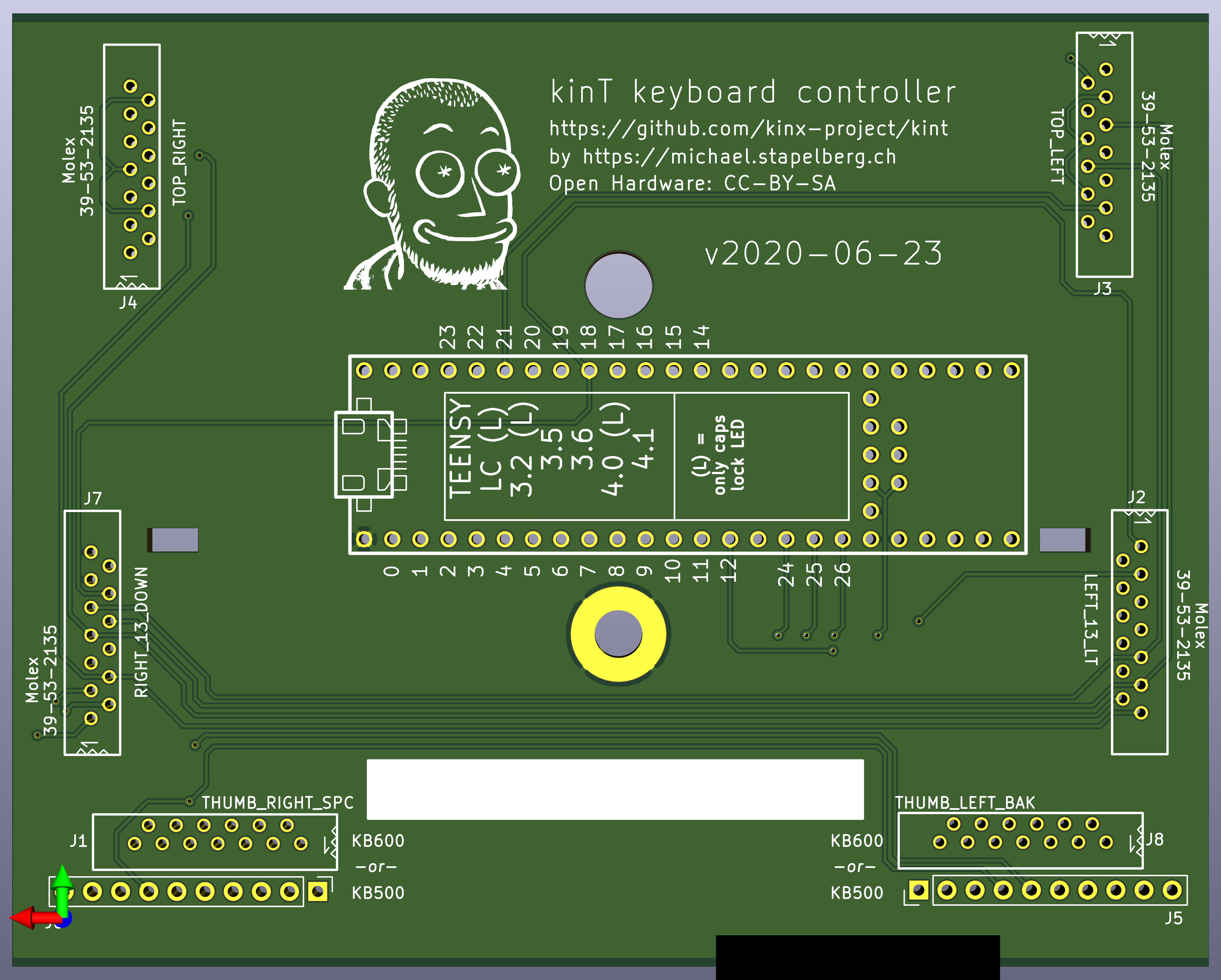
(<a href="https://raw.githubusercontent.com/kinx-project/kint/44e6c8be96a0e1e13ada5eafdeba8c51a2d6c9e8/pcb-3d-render-front-v2020-06-23.png">front</a>,
<a href="https://raw.githubusercontent.com/kinx-project/kint/44e6c8be96a0e1e13ada5eafdeba8c51a2d6c9e8/pcb-3d-render-back-v2020-06-23.png">back</a>)
and
<a href="https://github.com/kinx-project/kint/blob/44e6c8be96a0e1e13ada5eafdeba8c51a2d6c9e8/schematic-v2020-06-23.pdf">schematic</a>
are much much clearer, making assembly a breeze.</p>
</li>
<li>
<p>The kinT is a good starting point for your own project:</p>
<ul>
<li>
<p>kinT was designed in the open source <a href="https://kicad-pcb.org/">KiCad</a>
program, meaning you do not need any license subscriptions.</p>
</li>
<li>
<p>The clear silkscreen and schematic make development and debugging easier.</p>
</li>
</ul>
</li>
<li>
<p>On the kinT, the Teensy no longer has to be soldered onto the board upside down.</p>
</li>
<li>
<p>On the kinT, the FPC connectors have been moved for less strain on the cables.</p>
</li>
<li>
<p>The kinT makes possible lower-cost builds: if you don’t need the scroll lock,
num lock and keypad LEDs, you can use a Teensy LC for merely 11 USD.</p>
</li>
</ul>
<h2 id="conclusion">Conclusion</h2>
<p>I’m very excited to release this new keyboard controller, and I can’t wait to
see all the custom builds and modifications!</p>
<p>By the way, there is also a (4-hour!) <a href="https://youtu.be/I0kwQbnhlfk">stream
recording</a> in case you are interested in some more
history and context, and want to see me solder a kinT controller live on stream!</p>
]]></content>
  </entry>
  <entry>
    <title type="html"><![CDATA[kinX: latency measurement]]></title>
    <link href="https://michael.stapelberg.ch/posts/2018-04-17-kinx-latency-measurement/"/>
    <id>https://michael.stapelberg.ch/posts/2018-04-17-kinx-latency-measurement/</id>
    <published>2018-04-17T17:51:00+02:00</published>
    <content type="html"><![CDATA[<p>This post is part of a <a href="/posts/2018-04-17-kinx">series of posts about the kinX project</a>.</p>
<h3 id="latency-measurement">Latency measurement</h3>
<p>End-to-end latency consists of 3 parts:</p>
<ol>
<li>input latency (keyboard)</li>
<li>processing latency (computer)</li>
<li>output latency (monitor)</li>
</ol>
<p>During the development of the kinX keyboard controller, I realized that
measuring processing latency was quite simple with my hardware: I could start a
timer when sending a key press HID report to the computer and measure the
elapsed time when I would receive a reply from the computer.</p>
<p>The key to send is the Caps Lock key, because unlike other keys it results in a
reply: a HID report telling the keyboard to turn the Caps Lock LED on.</p>
<img src="/Bilder/kinx-latency-measurement-device.svg">
<h3 id="measurement-device">Measurement device</h3>
<p>To make this measurement technique accessible to as many people as possible, I
decided to pull it out of my kinX keyboard controller and instead build it using
the FRDM-K66F evaluation board, which uses the same microcontroller.</p>
<p>The FRDM-K66F can be bought for about 60 USD at big electronics shops, e.g. Digi-Key.</p>
<p>Find the firmware at <a href="https://github.com/kinx-project/measure-fw">https://github.com/kinx-project/measure-fw</a></p>
<h3 id="baseline">Baseline</h3>
<p>To determine the lowest processing latency one can possibly get for userspace
applications on a Linux system, I wrote a small program which uses Linux’s evdev
API to receive key presses and react to a Caps Lock keypress as quickly as it
can by turning the Caps Lock LED on.</p>
<p>Find the program at <a href="https://github.com/kinx-project/measure-evdev">https://github.com/kinx-project/measure-evdev</a></p>
<p>The following layers are exercised when measuring this program:</p>
<ul>
<li>USB host controller</li>
<li>Linux kernel (USB and input subsystems)</li>
<li>input event API (evdev)</li>
</ul>
<p>Notably, graphical interfaces such as X11 or Wayland are excluded.</p>
<p>The measurements can be verified using Wireshark’s usbmon capturing, which
provides a view of the USB bus from the computer’s perspective, excluding USB
poll latency and USB transaction time.</p>
<p>Using Ubuntu 17.10, I measured a processing latency of 152 μs on average.</p>
<h3 id="emacs">Emacs</h3>
<p>Now let’s see whether my current editor of choice adds significant latency.</p>
<p>Using a few lines of Emacs Lisp, I instructed Emacs to turn on the Caps Lock LED
whenever a key is inserted into the current buffer. In combination with
remapping the Caps Lock key to any other key (e.g. “a”), this allows us to
measure Emacs’s processing latency.</p>
<p>On the same Ubuntu 17.10 installation used above, Emacs 25.2.2 adds on average
278 μs to the baseline processing latency.</p>
<p>Find the code at <a href="https://github.com/kinx-project/measure-emacs">https://github.com/kinx-project/measure-emacs</a></p>
<h3 id="end-to-end-latency">End-to-end latency</h3>
<p>With the kinX keyboard controller, we can achieve the following end-to-end latency:</p>
<table>
	<thead>
			<tr>
					<th>contributor</th>
					<th>latency</th>
			</tr>
	</thead>
	<tbody>
			<tr>
					<td>Matrix scan</td>
					<td>≈ 208 μs</td>
			</tr>
			<tr>
					<td>USB poll</td>
					<td>≈ 125 μs</td>
			</tr>
			<tr>
					<td>Linux</td>
					<td>≈ 152 μs</td>
			</tr>
			<tr>
					<td>Emacs</td>
					<td>≈ 278 μs</td>
			</tr>
	</tbody>
</table>
<p><br>This sums up to ≈ 763 μs on average. On top of that, we have output latency
within [0, 16ms] due to the 60 Hz refresh rate of our monitors.</p>
<p>Note that using a compositor adds one frame of output latency.</p>
<h3 id="input-latency-perception">Input latency perception</h3>
<p>A natural question to ask is how well humans can perceive input latency. After
all, keyboards have been manufactured for many years, and if input latency was
really that important, surely manufacturers would have picked up on this fact by
now?</p>
<p>I ran a little unscientific experiment in the hope to further my understanding
of this question at the most recent Chaos Communication Congress in Leipzig.</p>
<p>In the experiment, I let 17 people play a game on a specially prepared
keyboard. In each round, the game reconfigures the keyboard to either have
additional input latency or not, decided at random. The player can then type a
few keys and make a decision. If the player can correctly indicate whether
additional input latency was present in more than 50% of the cases, the player
is said to be able to distinguish latency at that level. On each level, the game
decreases the additional input latency: it starts with 100ms, then 75ms, then
50ms, etc.</p>
<p>The most sensitive player reliably recognized an additional 15ms of input
latency.</p>
<p>Some players could not distinguish 75ms of additional input latency.</p>
<p>Every player could distinguish 100ms of additional input latency.</p>
<p>My take-away is that many people cannot perceive slight differences in input
latency at all, explaining why keyboard manufacturers don’t optimize for low
latency.</p>
<p>Reducing input latency still seems worthwhile to me: even if the reduction
happens under the threshold at which you can perceive differences in input
latency, it buys you more leeway in the entire stack. In other words, you might
now be able to turn on an expensive editor feature which previously slowed down
typing too much.</p>
<h3 id="conclusion">Conclusion</h3>
<p>When I started looking into input latency, my keyboard had dozens of
milliseconds of latency. I found an easy win in the old firmware, then hit a
wall, started the kinX project and eventually ended up with a keyboard with just
0.33ms input latency.</p>
<p>Even if I had not reduced the input latency of my keyboard at all, I feel that
this project was a valuable learning experience: I now know a lot more about PCB
design, ARM microcontrollers, USB, HID, etc.</p>
<p>Typing on a self-built keyboard feels good: be it because of the warm fuzzy
feeling of enjoying the fruits of your labor, or whether the input latency
indeed is lower, I’m happy with the result either way.</p>
<p>Lastly, I can now decidedly claim that the processing latency of modern
computers is perfectly fine (remember our 152 μs + 278 μs measurement for
Linux + Emacs), and as long as you pick decent peripherals, your end-to-end
latency will be fine, too.</p>
<h3 id="whats-next">What’s next?</h3>
<p>By far the biggest factor in the end-to-end latency is the monitor’s refresh
rate, so getting a monitor with a high refresh rate and no additional processing
latency would be the next step in reducing the end-to-end latency.</p>
<p>As far as the keyboard goes, the matrix scan could be eliminated by wiring up
each individual key to a microcontroller with enough GPIO pins. The USB poll
delay could be eliminated by switching to USB 3, but I don’t know of any
microcontrollers which have USB 3 built-in yet. Both of these improvements are
likely not worth the effort.</p>
]]></content>
  </entry>
  <entry>
    <title type="html"><![CDATA[kinX: USB Hub]]></title>
    <link href="https://michael.stapelberg.ch/posts/2018-04-17-kinx-usb-hub/"/>
    <id>https://michael.stapelberg.ch/posts/2018-04-17-kinx-usb-hub/</id>
    <published>2018-04-17T17:50:00+02:00</published>
    <content type="html"><![CDATA[<p>This post is part of a <a href="/posts/2018-04-17-kinx">series of posts about the kinX project</a>.</p>
<h3 id="motivation">Motivation</h3>
<p>The Kinesis Advantage comes with a built-in 2-port USB hub. That hub uses a
proprietary connector to interface with a
<a href="https://en.wikipedia.org/wiki/PS/2_port">PS/2</a> keyboard controller, so it
cannot be used with a USB keyboard controller. As the built-in hub is the
natural place to connect the Logitech unified receiver dongle, not being able to
use the hub is mildly annoying.</p>
<p>The kinX MK66F keyboard controller presently needs two USB cables: one connected
to the USBFS port to supply the PCB with power and receive firmware updates (via
the Teensy bootloader chip), and one connected to the USBHS port for the actual
keyboard device.</p>
<p>Lastly, even if the original built-in USB hub had internal ports (instead of a
PS/2 converter), it only supports USB 1.1, nullifying any latency improvements.</p>
<p>Hence, I decided to build a drop-in replacement USB 2.0 hub with 2 external USB
ports and 2 internal USB ports, using the same proprietary connector as the
original, so that the original keyboard USB cable could be re-used.</p>
<h3 id="design-phase">Design phase</h3>
<p>Unfortunately, I could not find an open hardware USB 2.0 hub design on the
internet, so I started researching various USB hub chips. I quickly discarded
the idea of using USB 3 due to its much stricter requirements.</p>
<p>In the end, I decided to go with the Cypress HX2VL series because of their
superior documentation: I found a detailed data sheet, an evaluation board, the
associated schematics, design checklist/guidelines, and even the evaluation
board’s bill of materials.</p>
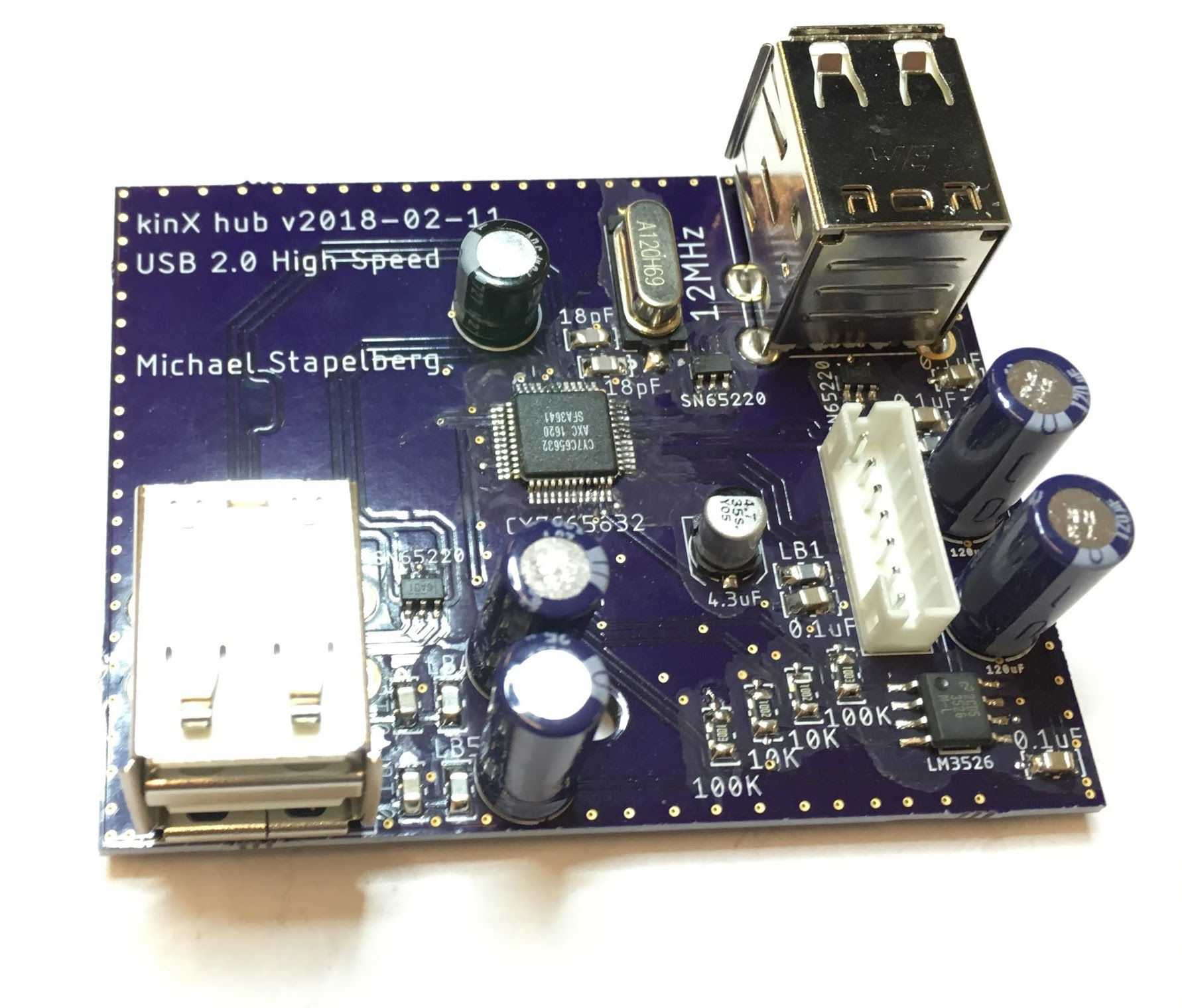
<p>This is what the finished build of my design looks like:</p>


<a href="https://michael.stapelberg.ch/posts/2018-04-17-kinx-usb-hub/kinx-hub.jpg"><img
  srcset="https://michael.stapelberg.ch/posts/2018-04-17-kinx-usb-hub/kinx-hub_hu_e901da1bad0eaf0d.jpg 2x,https://michael.stapelberg.ch/posts/2018-04-17-kinx-usb-hub/kinx-hub_hu_7f071769f8ba23cf.jpg 3x"
  src="https://michael.stapelberg.ch/posts/2018-04-17-kinx-usb-hub/kinx-hub_hu_9d68990b4aaaa316.jpg"
  alt="kinX USB Hub" title="kinX USB Hub"
  width="600"
  height="512"
  style="

border: 1px solid #000;

"
  
  loading="lazy"></a>


<h3 id="power">Power</h3>
<p>After completing my first build, I tested a few USB devices with my hub. The
Logitech unified receiver dongle and the
<a href="https://www.yubico.com/start/">YubiKey</a> worked fine. However, my external hard
drive and my USB memory stick did not work. In the syslog, I would see:</p>
<pre tabindex="0"><code>kernel: usb 1-14.4.4: rejected 1 configuration due to insufficient available bus power
</code></pre><p>This is because the USB specification limits bus-powered hubs to 100mA per
port. While high power usage does not come as a surprise for the external hard
disk, it turns out that even my USB memory stick requires 200mA. This was a
surprise, because that stick works on other, commercial bus-powered USB hubs.</p>
<p>A closer look reveals that all 3 commercial USB hubs I have tested claim to be
self-powered (i.e. using an external power supply), even though they are
not. This way, the kernel’s power limitation is circumvented, and up to 500mA
can be used per port. In practice, the host port only supplies 500mA, so the
user must be careful not to plug in devices which require more than 500mA in
aggregate.</p>
<p>I changed the SELFPWR configuration pin to have my hub claim it was
self-powered, too, and that made all USB devices I tested work fine.</p>
<h3 id="eeprom-programming">EEPROM programming</h3>
<p>When debugging the power issue, I originally thought the Maximum Power setting
in the hub’s USB device descriptor needed to be raised. This turned out to not
be correct: the Maximum Power refers to the power which the hub uses for its own
circuitry, not the power it passes through to connected devices.</p>
<p>Nevertheless, it’s a nice touch to modify the device descriptor to put in a
custom vendor name, product name and serial number: that way, the device shows
up with a recognizable name in your syslog or
<a href="https://manpages.debian.org/stretch/usbutils/lsusb.8"><code>lsusb(8)</code></a> output, and
udev rules can be used to apply settings based on the serial number.</p>
<p>To modify the device descriptor, an <a href="https://en.wikipedia.org/wiki/EEPROM">EEPROM (electrically erasable programmable
read-only memory)</a> needs to be added to
the design, from which the HX2VL will read configuration.</p>
<p>The HX2VL allows field-programming of the connected EEPROM, i.e. writing to it
via the USB hub chip. I found the Windows-only tool hard to set up on a modern
Windows installation, so I wondered whether I could build a simpler to use tool.</p>
<p>Under the covers, the tool merely sends commands with the vendor-specific
request code 14 via USB, specifying an index of the two-byte word to
read/write. This can be replicated in a few lines of Go:</p>
<pre tabindex="0"><code>dev, _ := usb.OpenDeviceWithVIDPID(0x04b4, 0x6570)
eepromRequest := 14
wIndex := 0 // [0, 63] for 128 bytes of EEPROM
dev.Control(gousb.RequestTypeVendor|0x80, 
  eepromRequest, 0, wIndex, make([]byte, 2))
</code></pre><p>The EEPROM contents are well-described in the <a href="http://www.cypress.com/file/114101/download">HX2VL data
sheet</a>, so the rest is easy.</p>
<p>See <a href="https://github.com/kinx-project/mk66f-blaster">https://github.com/kinx-project/mk66f-blaster</a> for the tool.</p>
<h3 id="lessons-learnt">Lessons learnt</h3>
<ul>
<li>
<p>If possible, design the PCB in such a way that components you think you don’t
need (e.g. the EEPROM) can optionally be soldered on. This would have saved me
a PCB design/fabrication cycle.</p>
</li>
<li>
<p>Get the evaluation board to figure out the configuration you need
(e.g. self-powered vs. bus-powered).</p>
</li>
</ul>
<h3 id="next-up">Next up</h3>
<p>The <a href="/posts/2018-04-17-kinx-latency-measurement/">last post introduces the processing latency measurement firmware for the
FRDM-K66F development board</a> and
draws a conclusion.</p>
]]></content>
  </entry>
  <entry>
    <title type="html"><![CDATA[kinX: keyboard controller with &lt;0.33ms input latency]]></title>
    <link href="https://michael.stapelberg.ch/posts/2018-04-17-kinx-keyboard-controller/"/>
    <id>https://michael.stapelberg.ch/posts/2018-04-17-kinx-keyboard-controller/</id>
    <published>2018-04-17T17:49:00+02:00</published>
    <content type="html"><![CDATA[<p>This post is part of a <a href="/posts/2018-04-17-kinx">series of posts about the kinX project</a>.</p>
<h3 id="background">Background</h3>
<p>10 years ago I got a Kinesis Advantage keyboard. I wrote about the experience of
learning to touch-type using the ergonomic <a href="https://neo-layout.org/">NEO layout</a>
in my (German) post <a href="/posts/2009-01-01-neo_kinesis/">“Neo-Layout auf einer
Kinesis-Tastatur”</a>.</p>
<p>The Kinesis Advantage is still the best keyboard I’ve ever used, and I use one
every day, both at the office and at home.</p>
<p>I had two reasons to start modifying the keyboard:</p>
<ol>
<li>
<p>I prefer Cherry MX blue key switches over the Cherry MX brown key switches
the Kinesis comes with. Nowadays, you can get a Kinesis with Cherry MX red
key switches, which felt okay in a quick test.</p>
</li>
<li>
<p>The original keyboard controller has (had?) a bug where modifier keys such as
Shift would get stuck at least once a week: you would press Shift, press A,
release A, release Shift, press A and see AA instead of Aa.</p>
</li>
</ol>
<p>I solved issue ① with the help of the excellent Kinesis technical support, who
sold me unpopulated PCBs so that I could solder on my own key switches.</p>
<p>Issue ② was what lead to my first own keyboard controller build, which I
documented in <a href="/posts/2013-03-21-kinesis_custom_controller/">“Hacking your own Kinesis keyboard
controller”</a> (2013).</p>
<p>Then, the topic of input latency popped into my filter bubble, with excellent
posts such as <a href="https://pavelfatin.com/typing-with-pleasure/">Pavel Fatin’s “Typing with
pleasure”</a>. I started wondering
what input latency I was facing, and whether/how I could reduce it.</p>
<p>Given that I was using a custom keyboard controller, it was up to me to answer
that question. After trying to understand and modify the firmware I had been
using for the last 4 years, I realized that I first needed to learn much more
about how keyboards work.</p>
<p>I firmly believe that creating a good environment is vital for development,
especially for intrinsically-motivated side projects like this one. Hence, I set
the project aside until a colleague gifted me his old Kinesis which had
intermittent issues. I removed the electronics and started using that keyboard
as my development keyboard.</p>
<h3 id="sources-of-input-latency">Sources of input latency</h3>
<p>A keyboard controller has 3 major tasks:</p>
<ul>
<li>
<p><strong>matrix scan</strong>: to avoid physically connecting every single key switch
directly to a microcontroller (requiring a large number of GPIO pins), most
keyboards use a matrix. See <a href="http://blog.komar.be/how-to-make-a-keyboard-the-matrix/">“How to make a keyboard — the
matrix”</a> for a good
explanation.</p>
</li>
<li>
<p><strong>debouncing</strong>: when pressing a key switch, it doesn’t cleanly change from a
low voltage level to a high voltage level (or vice-versa). Instead, it
bounces: the voltage level rapidly oscillates until it eventually reaches a
stable steady state. Because one key press shouldn’t result in a whole bunch
of characters, keyboard controllers need to debounce the key press.</p>
</li>
<li>
<p><strong>USB</strong>: nowadays, keyboards use USB (for example to be compatible with
laptops, which generally don’t have PS/2 ports), so the keyboard’s state needs
to be communicated to the computer via USB.</p>
</li>
</ul>
<p>Here’s an illustration of the timing of a key press being handled by a naive
keyboard controller implementation:</p>
<img src="/Bilder/kinx-input-latency-sources.svg">
<p>In the worst case, a key press happens just after a keyboard matrix scan. The
first source of latency is the time it takes until the next keyboard matrix scan
happens.</p>
<p>Depending on the implementation, the key press now sits in a data structure,
waiting for the debounce time to pass.</p>
<p>Finally, once the key press was successfully debounced, the device must wait
until the USB host polls it before it can send the HID report.</p>
<p>Unless the matrix scan interval is coupled to the USB poll interval, the delays
are additive, and the debounce time is usually constant: in the best case, a key
press happens just before a matrix scan (0ms) and gets debounced (say, 5ms) just
before a USB poll (0ms).</p>
<h3 id="teensy-36-controller-for-learning">Teensy 3.6 controller (for learning)</h3>
<p>My old keyboard controller used the
<a href="https://www.pjrc.com/teensy/index.html">Teensy++</a>, which is fairly dated at
this point. I decided a good start of the project would be to upgrade to the
current Teensy 3.6, cleaning up the schematics on the way.</p>
<img src="/Bilder/kinx-teensy36.jpg" width="100%">
<p>To ensure I understand all involved parts, I implemented a bare-metal firmware
almost from scratch: I cobbled together the required startup code, USB stack
and, most importantly, key matrix scanning code.</p>
<p>In my firmware, the Teensy 3.6 runs at 180 MHz (compared to the Teensy++’s 16
MHz) and scans the keyboard matrix in a busy loop (as opposed to on USB
poll). Measurements confirmed a matrix scan time of only 208μs (0.2ms).</p>
<aside class="admonition note">
  <div class="note-container">
    <div class="note-icon" style="width: 20px; height: 20px">
      <svg id="exclamation-icon" width="100%" height="100%" viewBox="0 0 24 24" version="1.1" xmlns="http://www.w3.org/2000/svg" xmlns:xlink="http://www.w3.org/1999/xlink" xml:space="preserve" style="fill-rule:evenodd;clip-rule:evenodd;stroke-linejoin:round;stroke-miterlimit:1.41421;">
    <path d="M0,0L24,0L24,24L0,24L0,0Z" style="fill:none;"/>
    <g transform="matrix(1.2,0,0,1.2,-2.4,-2.4)">
        <path d="M12,2C6.48,2 2,6.48 2,12C2,17.52 6.48,22 12,22C17.52,22 22,17.52 22,12C22,6.48 17.52,2 12,2ZM13,17L11,17L11,15L13,15L13,17ZM13,13L11,13L11,7L13,7L13,13Z" style="fill-rule:nonzero;"/>
    </g>
</svg>

    </div>
    <div class="admonition-content"><strong>Update:</strong> Previously, I had measured the matrix scan time as 100μs
(0.1ms). While that is technically correct, in practice, matrix scans take
longer due to interrupts, so the new 208μs measurement is more realistic.</div>
  </div>
</aside>

<p>I implemented debouncing the way it is described in <a href="https://summivox.wordpress.com/2016/06/03/keyboard-matrix-scanning-and-debouncing/">Yin Zhong’s “Keyboard
Matrix Scanning and
Debouncing”</a>:
by registering a key press/release on the rising/falling edge and applying the
debounce time afterwards, effectively eliminating debounce latency.</p>
<p>Note that while the Cherry MX datasheet specifies a debounce time of 5ms, I
found it necessary to increase the time to 10ms to prevent bouncing in some of
my key switches, which are already a few years old.</p>
<p>I set the USB device descriptor’s poll interval to 1, meaning poll every 1 USB
micro frame, which is 1ms long with USB 1.x (Full Speed).</p>
<p>This leaves us at an input latency within [0ms, 1.1ms]:</p>
<ul>
<li>≤ 0.2ms scan latency</li>
<li>0ms debounce latency</li>
<li>≤ 1ms USB poll latency</li>
</ul>
<p>Can we reduce the input latency even further? The biggest factor is the USB poll
interval.</p>
<h3 id="usb-high-speed">USB High Speed</h3>
<p>With USB 2.0 High Speed, the micro frame duration is reduced to 125μs
(0.125ms). The NXP MK66F micro controller in the Teensy 3.6 has two USB ports:</p>
<ol>
<li>the Full Speed-only USBFS port, which is used by the Teensy 3.6</li>
<li>the High Speed-capable USBHS port, which the Teensy optionally uses for host
mode, with experimental software support (at the time of writing)</li>
</ol>
<img src="/Bilder/kinx-usbhs-breakout.jpg" width="100%">
<p>While the software support was a road block which could conceivably be solved, I
also faced a mechanical problem: the available space in the Kinesis keyboard and
the position of the USB High Speed port pins on the Teensy 3.6 unfortunately
prevented installing any sort of breakout board to actually use the port.</p>
<p>I decided to move from the Teensy 3.6 to my own design with the same
microcontroller.</p>
<h3 id="mk66f-keyboard-controller">MK66F keyboard controller</h3>


<a href="https://michael.stapelberg.ch/posts/2018-04-17-kinx-keyboard-controller/kinx-mk66f.jpg"><img
  srcset="https://michael.stapelberg.ch/posts/2018-04-17-kinx-keyboard-controller/kinx-mk66f_hu_faff1a0bc945dbc2.jpg 2x,https://michael.stapelberg.ch/posts/2018-04-17-kinx-keyboard-controller/kinx-mk66f_hu_dfc9d3df328c2cbd.jpg 3x"
  src="https://michael.stapelberg.ch/posts/2018-04-17-kinx-keyboard-controller/kinx-mk66f_hu_c351fa97d4f6e10.jpg"
  alt="MK66F" title="MK66F"
  width="600"
  height="469"
  style="

border: 1px solid #000;

"
  
  loading="lazy"></a>


<p>To make development pleasant, I connected a USB-to-serial adapter (to UART0) and
a “rebootor” (to PROGHEAD): another Teensy with a special firmware to trigger
programming mode. This way, I could set my editor’s <code>compile-command</code> to <code>make &amp;&amp; teensy_loader_cli -r …</code>, compiling the code, uploading and booting into the
resulting firmware with a single keyboard shortcut.</p>
<p>I based the firmware for this controller on NXP’s SDK examples, to ensure I get
a well-tested and maintained USB stack for the USBHS port. I did some
measurements to confirm the stack does not add measurable extra latency, so I
did not see any value in me maintaining a custom USB stack.</p>
<p>The firmware can be found at <a href="https://github.com/kinx-project/mk66f-fw">https://github.com/kinx-project/mk66f-fw</a></p>
<p>The hardware can be found at <a href="https://github.com/kinx-project/mk66f-hw">https://github.com/kinx-project/mk66f-hw</a></p>
<p>Using USB 2.0 High Speed leaves us at an input latency within [0ms, 0.33ms]:</p>
<ul>
<li>≤ 0.2ms scan latency</li>
<li>0ms debounce latency</li>
<li>≤ 0.125ms USB poll latency</li>
</ul>
<h3 id="lessons-learnt">Lessons learnt</h3>
<ul>
<li>
<p>In the future, I will base custom designs on the vendor’s development board
(instead of on the Teensy). This way, the vendor-provided code could be used
without any modifications.</p>
</li>
<li>
<p>While the Teensy bootloader means getting started with the microcontroller
just requires a USB port, using a JTAG connector for development would be more
powerful: not only does it replace the combination of Teensy bootloader,
serial and rebootor, but it also supports debugging with gdb.</p>
</li>
</ul>
<h3 id="next-up">Next up</h3>
<p>The <a href="/posts/2018-04-17-kinx-usb-hub/">second post motivates and describes building a drop-in replacement USB
hub</a> for the Kinesis Advantage keyboard.</p>
]]></content>
  </entry>
  <entry>
    <title type="html"><![CDATA[kinX: overview]]></title>
    <link href="https://michael.stapelberg.ch/posts/2018-04-17-kinx/"/>
    <id>https://michael.stapelberg.ch/posts/2018-04-17-kinx/</id>
    <published>2018-04-17T17:48:00+02:00</published>
    <content type="html"><![CDATA[<p>The kinX project is described in a series of blog posts:</p>
<ul>
<li>
<p>While not strictly a part of this series, <a href="/posts/2013-03-21-kinesis_custom_controller/">“Hacking your own Kinesis keyboard
controller”</a> describes the first
controller I built in 2013 (maybe interesting for context).</p>
</li>
<li>
<p>The <a href="/posts/2018-04-17-kinx-keyboard-controller/">first post introduces the kinX, a keyboard
controller</a> with merely 0.33ms of
input latency (including USB).</p>
</li>
<li>
<p>The <a href="/posts/2018-04-17-kinx-usb-hub/">second post motivates and describes building a drop-in replacement USB
hub</a> for the Kinesis Advantage keyboard.</p>
</li>
<li>
<p>The <a href="/posts/2018-04-17-kinx-latency-measurement/">last post introduces the processing latency measurement firmware for the
FRDM-K66F development board</a> and
draws a conclusion.</p>
</li>
</ul>
<p>You can find the project’s artifacts at <a href="https://github.com/kinx-project">https://github.com/kinx-project</a>.</p>
]]></content>
  </entry>
</feed>